Comtrol ES7510-XT User Manual
Page 75
RocketLinx ES7510-XT User Guide: 2000571
Rev. D
PoE Control - 75
Configuration Using the Web Interface
Voltage (V)
This is the voltage applied to the power supply. Typically, you should use the same value for
DC1 and DC2, otherwise the ES7510-XT draws more current from the power supply with
the highest voltage.
Power Budget
Warning Level
If the power utilization is more than the warning level, the ES7510-XT sends a warning
event. The range is 0-100%. 0 is disabled.
Port Configuration
PoE Mode
You can select Disable, Enable, or Schedule for PoE mode for each port. Select Schedule to
enable the port in the PoE Schedule page (
).
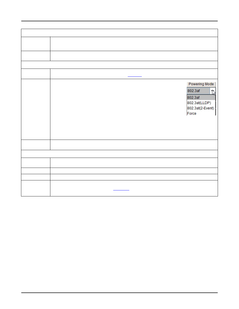
Powering
Mode
Use this mode to change the Powering Mode to one of the following:
•
802.3af If the PD follows IEEE 802.3af, then the ES7510-XT delivers
power.
•
802.3at(LLDP) Delivers power to a PD that supports IEEE 802.3a
t
LLDP.
•
802.3at(2-Event) Delivers power to a PD that supports 2-Event.
•
Force If Force is enabled, the port directly delivers the power even if
there is no Ethernet cable connected.
To enable IEEE 802.3at High Power PoE functionality, the power input voltage should be
over 55VDC for better performance.
Note: Use caution when using Force mode. Do not connect a standard Ethernet device if
using Force mode, it will damage the device.
Power Budget
(W)
The power supply output ability that is installed with PoE Switch. A pop-up warning
message appears when the PoE port setting is over the system power supply output ability.
PD Status Detection
PD Status
Detection
Enable/Disable the PD Status Detection function.
IP Address
Type in the IP address that you want to detect.
Cycle Time(s)
This is the gap per detection in seconds.
Apply
Click Apply to apply the settings.
Note: You must Save the settings (
), if you want maintain these settings if the
ES7510-XT is powered off.
PoE Control (Continued)