Toshiba, 8 pid set point control – Toshiba Q-Flowsaver II User Manual
Page 58
Attention! The text in this document has been recognized automatically. To view the original document, you can use the "Original mode".
TOSHIBA
10.8
PID Set Point Control
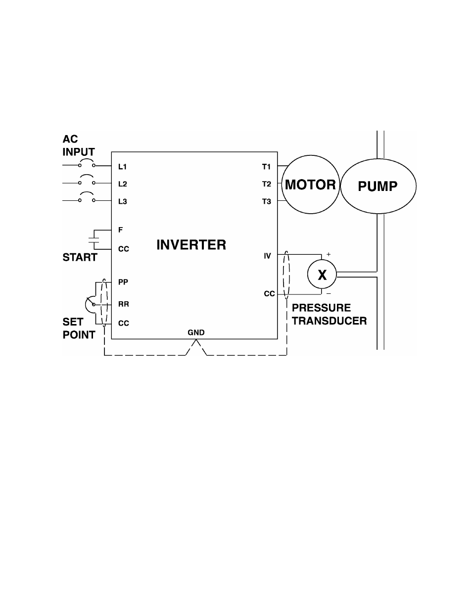
All Q-Flowsaver II inverters come standard with set point control. The following
information shows how to install and adjust the inverter using set point control. The
feedback signal should be either 0-5 volts or a 4-20mA current. It is connected to
terminals IV and CC. The set point is adjusted by using a potentiometer. The diagram
below shows how a potentiometer should be connected to terminals PP, RR, and CC
to control the setpoint. Each of these connections are made to the Control/Driver
Board terminal block (see detail Page 5-5). The connection diagram below shows
the necessary wiring.
Use the following procedures to adjust the setpoint control parameters:
INITIAL SETUP
1)
Remove power and place the jumper connections JP1 and JP2 (See detail 1 or 2
Page 5-5 and Jumper/Terminal Connections and Functions Page 5-6) in the correct
positions for the type of feedback signal used; power can then be applied again.
2)
Set acceleration and deceleration times to 5 seconds (see Setup Parameters
Item # 1 and 2).
3)
Adjust the bias and gain for the systems feedback signal. For example, typically the
motor slows down when the feedback signal goes above the setpoint. This action
can be reversed by exchanging the data between F-P1 and F-P2 (see Setup
Parameters Item # 6 and 8).
4)
Turn on the set point (PID) control (see Jump Frequency Group parameters Item #7).
5)
Set proportional gain to 250 (see Jump Frequency Group parameters Item #8).
6)
Set integral gain to 100 (see Jump Frequency Group parameters Item #9).
7)
Set differential gain to 0 (see Jump Frequency Group parameters Item #10).
8)
Set lag-time constant to 255 (see Jump Frequency Group parameters Item #11).
9)
Run system.
1 0 - 5