2 control/driver board for q2-4055 through q2-4330, Toshiba – Toshiba Q-Flowsaver II User Manual
Page 20
Attention! The text in this document has been recognized automatically. To view the original document, you can use the "Original mode".
TOSHIBA
5.2
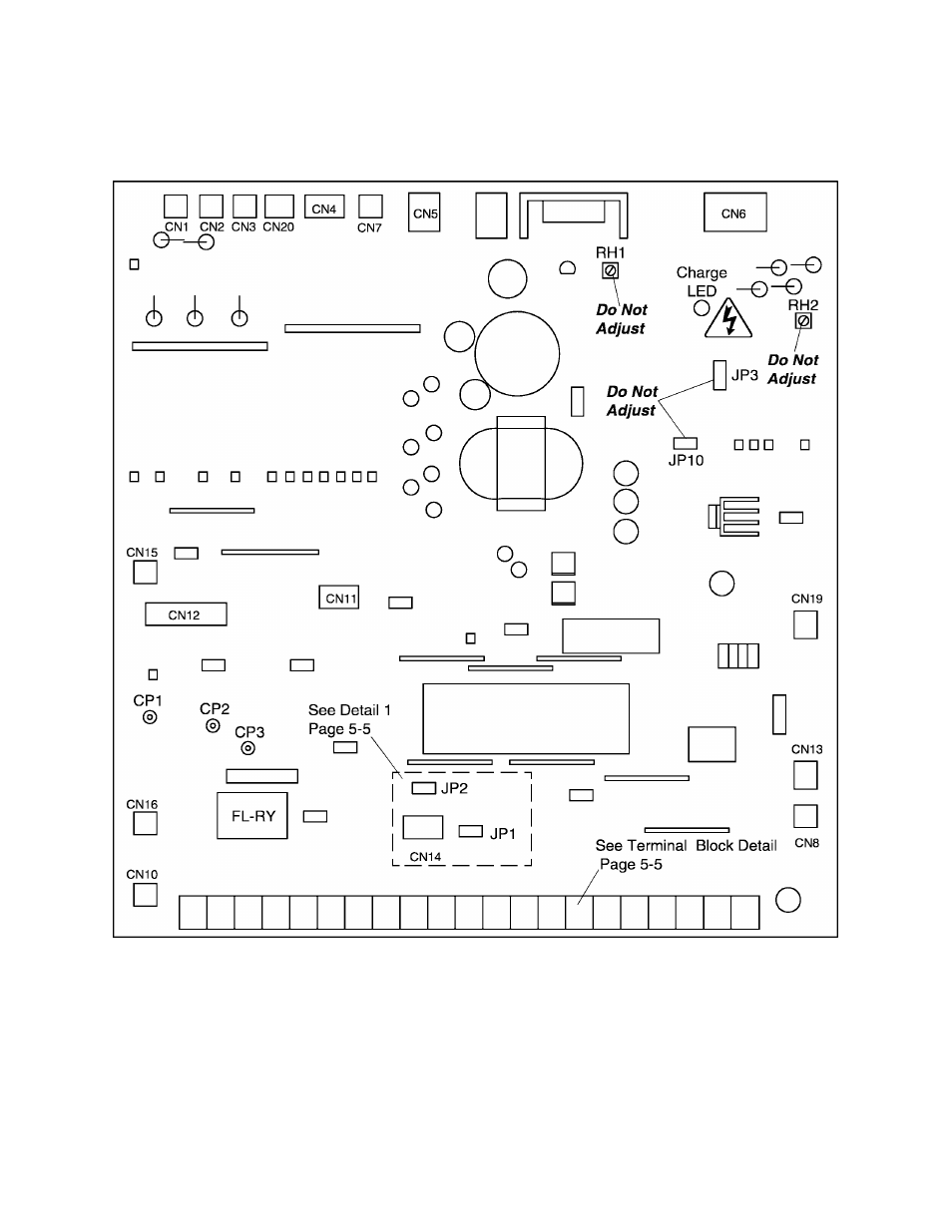
Control/Driver Board for Q2-4055 through Q2-4330
The following pictorial shows a layout of the major components located on the
control/dhver board VF3B-0101.
Note:
1)
Potentiometer
RH1
is used for control power supply stabilization. This adjustment is
factory set and any
ADJUSTMENT BY THE USER SHOULD NOT BE ATTEMPTED.
2)
Potentiometer
RH2
is used for voltage detection level bias. This adjustment is factory
set and any
ADJUSTMENT BY THE USER SHOULD NOT BE ATTEMPTED.
3)
CP1, CP2, and CP3 are service testpoints.
4)
Do not adjust JP3 and JP10.
5)
Charge LED indicates charged capacitors.
DO NOT TOUCH internal parts if lighted.
5 - 2
- Power Inverter (15 pages)
- 1800 (6 pages)
- TOSVERT VF-S11 (68 pages)
- Uninterruptible Power System G9000 (104 pages)
- Density (Consistency) Meter LQ500 (9 pages)
- MBSB80-225-43 (1 page)
- TOSNIC-7000S (53 pages)
- 1600EP Series (3 pages)
- 1500 (32 pages)
- TOSVERT VF-FS1 Series (16 pages)
- 4200FA XT1 (1 page)
- G3 Plus Pack (4 pages)
- Tosvert VF-A5 (149 pages)
- 1600 Series (3 pages)
- G9000 (100 pages)
- TEC EO1-33030 (54 pages)
- 1000 Series (2 pages)
- 1500 Plus (31 pages)
- G8000MM (6 pages)
- VT130G1 (99 pages)
- 4200FA Series (2 pages)
- VF-PS1 (10 pages)
- GX7 Series (6 pages)
- 4200FA XT (1 page)
- RMTI-EMD-HT (2 pages)
- W7 Series (6 pages)
- HX7 (6 pages)
- PDP002Z (18 pages)
- RELIABILITY IN MOTION 1700 (39 pages)
- 1700 Series (2 pages)
- G3 TOSVERT-130 (62 pages)
- B-852-TS12-QP (55 pages)
- 1000 (4 pages)
- E3 (7 pages)
- Adjustable Speed Drive H3 (122 pages)
- 55611-001 (2 pages)
- Black Gold Series (2 pages)
- Dura-Bull TX (6 pages)
- Current Relay RC803A-HP1 (19 pages)
- 1800 SERIES (2 pages)
- Isolated-Redundant UPS System (2 pages)
- Tosvert VF-AS1 (312 pages)
- RELIABILITY IN MOTION 1000 (54 pages)
- REMOTE-D (2 pages)
- 15-80KVA (2 pages)