7 jumper/terminal connections and functions, 0 olo, Jumper/terminal connections and functions -6 – Toshiba Q-Flowsaver II User Manual
Page 24: Toshiba, Oc 0 o, R0 y
Attention! The text in this document has been recognized automatically. To view the original document, you can use the "Original mode".
TOSHIBA
5.7
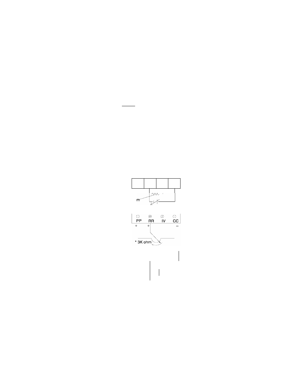
Jumper/Terminal Connections and Functions
The following table shows how jumpers JP1 and JP2 are set for use with the analog
input terminal connections RR and IV. Jumper numbers and settings which are shown in
this table are applicable to all printed wiring boards (see page 5-5 for terminal block
and jumper details).
Terminal/Jumper Connections for Input Reference Signals
JP1
JP2
Terminal Connections
Function
i V
0 olo
10V 5V
I
'vJ
I
'v.3
No external connections; JP1 and
JP2 should be set as shown for
keypad operation (normal factory
settinoV_______________________
Use when not inputting any external
reference signals into terminal RR or
IV. P.PrG parameter #2 "priority of
RR terminal input" is N/A.
I V
PP
0
RR
IV
CC
N/A
0-20mA
(4-20mA)
Use when inputting a 4(0)-20mA
external reference signal to terminal IV.
P.PrG parameter #2 "priority of RR
terminal input" should be set to 0 "on".
See page 7-5.
I V
O
PP
RR
IV
0
CC
N/A
Use when inputting 0-5Vdc external
reference signal to terminal IV.
P.Prg parameter #2 " priority of RR
terminal input" should be set to 0 "on"
See page 7-5.
0-5Vdc
N/A
0
PP
0
RR
0
IV
0
CC
+
—
15Koh
Use when inputting 0-1 OVdc external
reference signal to terminal RR.
P.Prg parameter #2 " priority of RR
terminal input" should be set to 1 "on".
See page 7-5.
0-1 OVdc
N/A
10V 5V
I 0.") 'vJ I 00
Use when inputting 0-1 OVdc external
reference signal to terminal RR.
P.Prg parameter #2 " priority of RR
terminal input" should be set to 1 "on".
See page 7-5.
10V 5V
0
( ' < \ ( ' i
o
c
0
o
PP
RR
IV
CC
+
+
f
r -
A
•
.
-r0
y'“
SW s.„ ---
0-20mA
(4-20mA)
Use when inputting a 4(0)-20mA
external reference signal to terminal IV
and a 0-1 OVdc reference signal to
terminal RR.
P.PrG parameter #2 "priority of RR
terminal input" should be set to 1 "on".
Terminal RR will override "have priority
over" terminal IV when switch (SW) is
closed.
See page 7-5.
3K ohm pot divides voitage between terminal PP and CC return. Any pot value between 1K to 10K ohms
can be used but makes adjustment more sensitive.
5 - 6