5 jumper details, 6 control/driver board terminal block details, Jumper details -5 – Toshiba Q-Flowsaver II User Manual
Page 23: Control/driver board terminal block details -5, Toshiba
Attention! The text in this document has been recognized automatically. To view the original document, you can use the "Original mode".
TOSHIBA
5.5
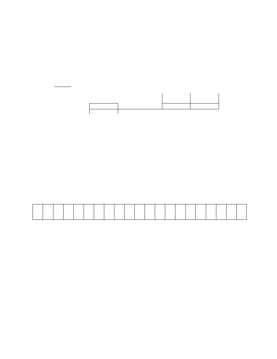
Jumper Details
The jumper connections for each of the printed wiring boards on Pages 5-1 through
5-3 are shown in the enlarged details below.
Only jumpers JP1 and JP2 should be
adjusted by the user.
See Page 5-6 for jumper adjustments.
10V 5V
I Q O l O
JP2
IV 1 1
1 1
I V
10V 5V
o i n n i
1 1
1 1
l O O l O
O l O O I
1
IP1
JP2
Detail 2 (Reference page 5-3)
Detail 1 (Reference pages 5-1 and 5-2)
Note:
Jumper settings as shown in these illustrations are for reference purposes only and do
not necessarily reflect factory settings nor correct settings for a particular application.
5.6
Control/Driver Board Terminal Block Details
The control/driver board terminal block is shown in detail below. Each of the twenty-one
terminals is functionally labeled. See Pages 5-7 and 5-8 for a list of terminal functions.
Control/Driver Board Terminal Block Detail (Reference pages 5-1,5-2, and 5-3)
© © © © © © © © © © © © © © © © © © © © ©
FLA FLB FLC P24 RCH LOW FM AM PP RR IV CC ST F R CC SSI JOG AD2 RST CC
(UL) (LL)
(SS2) (SS3)
5 - 5