4 connecting the bl-n70rke, Connecting the bl-n70rke -6, Connecting the bl-n70rke – KEYENCE BL-N70 Series User Manual
Page 20: Z communication settings
2-6
2
Conne
ct
ion
s
2-4
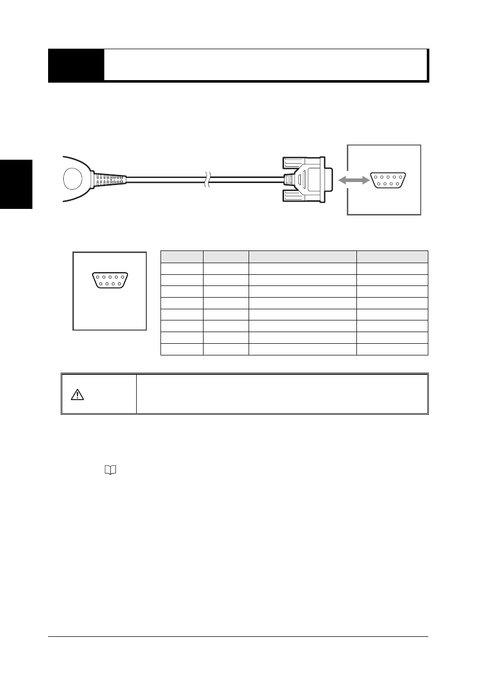
Connecting the BL-N70RKE
BL-N70RKE can be connected to the AutoID data controller DV-90 and to the dedicated
communication units BL-U1, BL-U2, and N-42. These components have a regulated 5VDC
power supply on Pin 9 of the D-sub connector.
Connector pins for BL-N70RKE
z Communication Settings
The following values represent factory settings for the BL-N70RKE. The settings can be
changed (
page 4-22). Make sure that the settings for BL-N70RKE and the connected
equipment are the same.
• Baud rate
: 9600 bit/s
• Data length
: 7 bits
• Parity
: Even
• Stop bit
: 1 bits
• Communication protocol : No protocol
CAUTION
Although it may be possible to connect the BL-N70RKE to external power
supplies, it is not recommended. Applying more than 5VDC +/-5% may
damage the scanner.
BL-N70RKE
To Keyence
products
(D-sub 9-pin)
Pin No.
Symbol
Description
Signal direction
2
RD (RXD)
Receives data
Input
3
SD (TXD)
Sends data
Output
4
-
Does not make any connection
-
5
SG
Signal ground
-
6
-
Does not make any connection
-
7
RS (RTS)
Request to send data
Output
8
CS (CTS)
Ready to send data
Input
9
Vcc
Inputs +5V DC power supply
Input
D-sub 9-pin (female)
#4-40 screws