2 table of indicated states, Appe ndi ces – KEYENCE SJ-F100W/100/010 User Manual
Page 45
2 Table of Indicated States
A-3
Appe
ndi
ces
Indicated states when settings are changed or confirmed, and during
operation (excluding when power is turned ON)
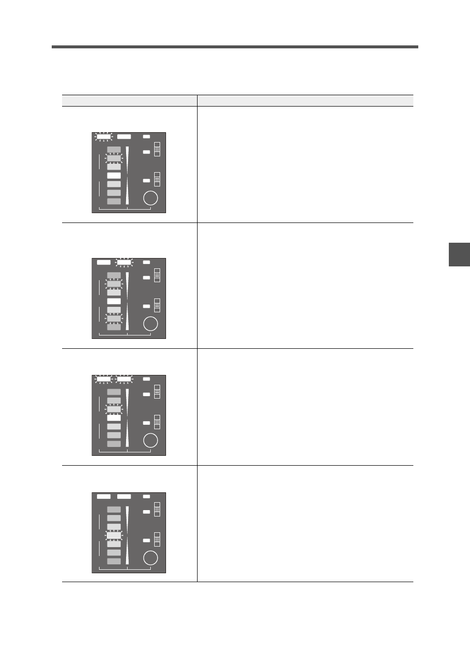
Lit State
Description
One of the ion monitor LEDs and the ion
balance indicator light (red).
Charged level indication
This indicates the charged level of the target object. When there is
a plus charged object, the LEDs on the upper side (+ side) light,
and when there is a minus charged object, the LEDs on the lower
side (- side) light according to the charged level.
One each of the plus and minus side
LEDs of the ion monitor, and the ion level
indicator light (red).
Ion level indication
This indicates the level of ions that are being generated by the SJ-
F100W/100/010.
Charged level indication or ion level
indication
Display selection
The display switches to the charged level indication when the
display selector key is pressed while the ion level is indicated.
When the charged level is indicated, the display switches to the
ion level indication.
The center LED of the ion monitor blinks
(red).
Static elimination stop input (I/O terminal section)
The center LED of the ion monitor blinks (red) when the static
elimination stop input and 0V terminals are shorted to stop static
elimination.
+
–
0
BALANCE
ION
ION
LEVEL
COND
DISP
ALARM
H
M
L
H
M
L
+
–
0
BALANCE
ION
ION
LEVEL
COND
DISP
ALARM
H
M
L
H
M
L
+
–
0
BALANCE
ION
ION
LEVEL
COND
DISP
ALARM
H
M
L
H
M
L
+
–
0
BALANCE
ION
ION
LEVEL
COND
DISP
ALARM
H
M
L
H
M
L