Conventions used in this manual, Terminology, Page configuration and symbols terminology – KEYENCE SJ-F100W/100/010 User Manual
Page 11: Connection and installation
ix
Conventions Used In This Manual
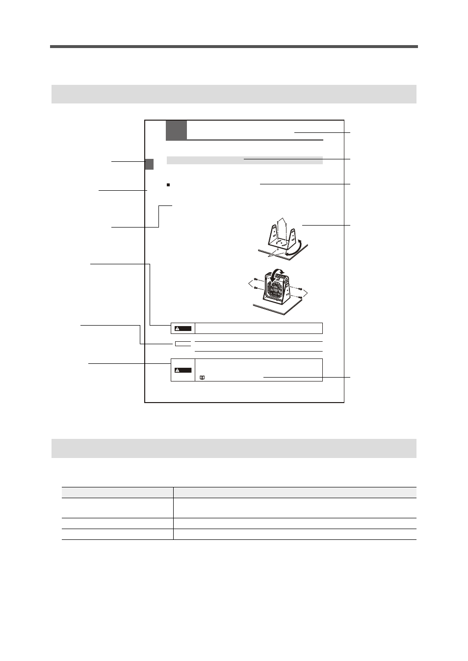
The following shows how pages are configured, and the symbols and terminology used in this manual.
Page Configuration and Symbols
Terminology
This manual uses the following terminology excluding some instances.
2-4
2
Connection and Inst
all
at
io
n
2-2
Connection and Installation
This section describes how to connect and install the Static Elimination Blower Unit and Controller Unit.
Installing the SJ-F100W/100/010
Install the SJ-F100W/100/010 at locations where static electricity is generated or is likely to be
generated.
Installing the Static Elimination Blower Unit
There are two ways of installing the Static Elimination Blower Unit, with or without the mounting fixtures.
When using mounting fixture A:
1
Tap M4 screw holes where the Static Elimination Blower Unit is to be installed, and fasten
mounting fixture A (OP-51409) with the M4 screws.
You can adjust the horizontal angle of the
Static Elimination Blower Unit by using the
semi-circled cutout holes on the base of
mounting fixture A.
The M4 screws for fastening mounting
fixture A at the installation location must
be provided separately.
2
Install the Static Elimination Blower Unit on mounting fixture A.
You can adjust the vertical angle
of the Static Elimination Blower
Unit by using the semi-circled
cutout holes on the base of
mounting fixture A.
The M4 screws for fastening
mounting fixture A to the Static
Elimination Blower Unit are
provided with mounting fixture A.
Install the Static Elimination Blower Unit so that it can be easily accessed, for
example, for replacement of parts and cleaning.
M4 screws
M4 tapped holes
To prevent electric shock and to ensure accurate static elimination, be sure to
connect a Class D earth (maximum resistance of 100 Ohms).
• Install the Static Elimination Blower Unit away from the wall or surrounding
objects.
• Install the Static Elimination Blower Un it so that the Electrode Unit can be
removed for replacement.
"Installation precautions" page 2-3
SJ-F0
10
M4 screws
M4 screws
WARNING
Note
CAUTION
Thumbnail index
Indicates the chapter.
Chapter title
Operational step
Warning
The user may be subjected
to physical harm (electric
shock, burns, etc.) if he
does not observe the
particulars described here.
Caution
Failure to observe the
caution described here may
result in product trouble.
Note:
Describes cautions for
easily mistaken operations.
Be sure to read these.
Headline
Mid-heading
Sub-heading
Illustration
Reference page
Indicates the page to
refer to. The page
containing the related
information is
indicated here.
* This page was made for the purpose of explaining page components,
and differs form an actual page.
Term
Description
SJ-F100W/100/010
General term for the Compact Static Elimination Blower SJ-F100W/100/
010
Static Elimination Blower Unit
SJ-F010
Controller Unit
SJ-F100W/100