Controller unit (i/o terminal section), Controller unit (i/o terminal section) -6, Input circuit diagram output circuit diagram – KEYENCE SJ-F100W/100/010 User Manual
Page 18
1-3
Names and Functions of Parts
1-6
1
Ab
out
t
he
Stat
ic
Eli
mi
nat
ion
Blo
w
er
Un
it
SJ-F1
00W/
100
/01
0
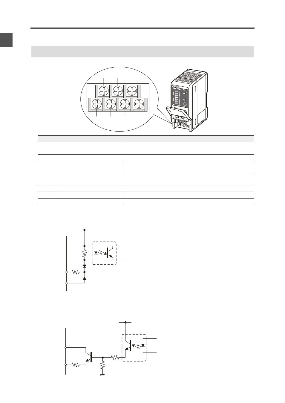
Controller Unit (I/O terminal section)
Input circuit diagram
Output circuit diagram
Number
Name
Function
(1)
Condition alarm output terminal
Outputs when static elimination performance is influenced by
instability in the installation environment.
(2)
Ion level alarm output terminal
Outputs when the ion emission level drops.
(3)
Static elimination stop input
terminal
Static elimination can be turned ON/OFF by shorting this terminal
with (6).
(4)
Ground terminal
Be sure to connect a Class D earth (maximum resistance of 100
Ohms).
(5)
DC power terminal
24 VDC ±10%
(6)
0V terminal
0V for power and 0V for I/O
(7)
Alarm output terminal
Outputs when an alarm occurs.
+
–
0
BALANCE
ION
ION
LEVEL
COND
FAN SPE
ED
SLOW
24V DC
OV
ALARM
CONDITIO
N
INTERRUP
T
ION LEV
EL
FAST
DISP
H
M
L
H
M
L
ALAR
M
SJ-F100W
ION BALA
NCE
ADJAST
(1)
(2)
(3)
(4)
(5)
(6)
(7)
[(3) (static elimination stop input)
+24V
3k
INPUT((3))
0V ((6))
Input a no-voltage contact (relay, etc.) or
NPN open collector to INPUT and 0V.
OUT
40 VDC
100 mA
Open collector output
[(2) (ion level alarm output), (1) (condition alarm output), (7) (alarm output)]
3.9
+24V
0V ((6))