Received light waveform display, Received light waveform display -28 – KEYENCE LK-HD1001 User Manual
Page 46
2-28
2
2 Screen Functions and Operation
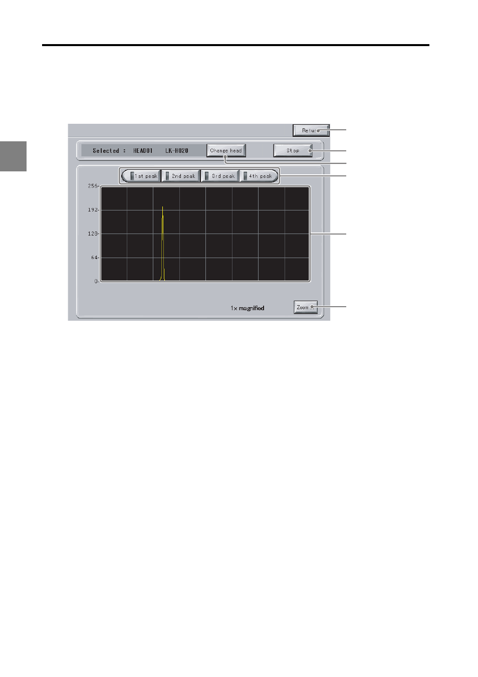
Received Light Waveform Display
This section explains the "Received light waveform display" function available on the touch panel.
Touching "Waveform" on the measurement screen displays the waveform display screen.
(1) Return
Returns to the measurement screen.
(2) Change head
Displays the "Select head" dialog box. Select which head to display the received light
waveform for.
(3) Start/Stop
Starts acquiring received light data from the controller and displays the most recent waveform.
Clicking "Start acquisition" causes the button label to change to "Stop".
(4) 1st peak to 4th peak
If "Measurement mode" is set to "Transparent2", these buttons will apply ABLE processing
to the displayed peak waveforms from 1 to 4, and display the resulting waveform. Refer to
the LK-G5000 series User's Manual, "Chapter 3 Function Settings" (page 3-1) for details on
the ABLE function.
(5) Received light waveform display
Displays the waveform after the controller applies ABLE processing. The waveform is read
as follows.
• X axis: Position of received light waveform. The farther left the waveform, the closer the
received light waveform is to the head.
• Y axis: Intensity of received light. The higher the waveform, the stronger the light intensity.
(6) Zoom in/Zoom out
Zooms in or out the waveform display.
(5)
(4)
(1)
(6)
(2)
(3)