Checkline TI-UMX2 User Manual
Page 22
– 22 –
7.0 MaKInG MeasureMenTs
The steps involved in making measurements are detailed in this section. The following
sections outline how to setup and prepare your TI-UMX2 for field use. An automatic or
manualzeromustalwaysbeperformedwhenusingadualelementstyletransduceronly.
The single element membrane probe option uses a special multiple echo mode, and does
notrequirezeroing.
Theautozeroisanoffblockelectroniczerothatdoesnotrequireazeroreferenceblock.
Thiswillmostalwaysbethezerooptionofchoice,asitmakesthezeroingprocessvery
easyandconvenienttoperform.However,ifthemanualzerooptionisenabled,the
probezeromustbemeasuredonthereferencediskattachedtothebottomendcapofthe
instrument.Thezerocompensateselectricalvariationsanddelaysforagiventransducer.
Likeamechanicalzero,it’sareferencepoint.Inallmodesthesoundvelocitymustbe
determined. The sound velocity is used to convert the transit time to a physical length.
The sound velocity can be selected from a preset list of material types in the TI-UMX2,
or can be programmed with a custom velocity using DataComm utility software. Refer
to section 7.3 for further info.
7.1 auto Probe recognition
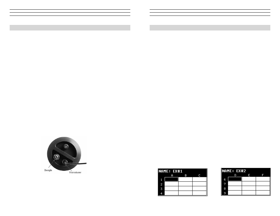
The first step in using the TI-UMX2 is to plug the transducer into the gauge and
power the unit up. If a single element style transducer is used, be sure that the dongle
is connected to the correct LEMO connector, as shown at right. The TI-UMX2 has a
special built-in automatic probe recognition feature that will check to see if the probe
plugged into the gauge was correctly identified.
noTe: Only custom Electromatic Ultrasonics transducers will work with the
TI-UMX2.
1. Connect the probe to the TI-UMX2.
2. Be sure all couplant has been removed from the face of the transducer.
3. Press and release the single button located on the end of the TI-UMX2. The displays
should illuminate, and led lights will begin flashing.
– 35 –
11.0 daTa sToraGe – seTuP, edIT, & VIeW fIles
11.1 Introduction to Grid and Sequential ile formats
The TI-UMX2 is equipped with two data file format options, GRID LOG and SEQ
LOG. The GRID file format is very similar to a spreadsheet format found in popular
software programs like Excel. A GRID is simply a table of readings. A location in a
grid is specified by giving a row and column coordinate. The rows are numbered from
1 to 999 and the columns are labeled from A to ZZ (999 Rows & 52 Columns). The
sequential file format can be viewed as a file as a single column of up to 512 possible
rows (readings), and a column of corresponding identifiers associated with each
individual reading. The identifier can be a combination of up to 10 numeric, alpha, or
special characters listed above, while the file name can consist of a combination of up
to 20 of the same character set. Note: The identifier cannot start or end with a special
character. Once a start and end ID are entered into the TI-UMX2 and the log created, the
TI-UMX2 will automatically generate all the identifiers within that range.
The following character set listed below are all the allowable characters that will be
used for both file formats: GRID & SEQ LOG. Any combination of these characters can
be used for creating a Name and Note regardless of the selected format. The allowable
characters are as follows:
Numeric characters: 0 – 9 Alpha Characters: A – Z
Special Characters:
!‘_#space/.–()
noTe: Multiple grids can be created and saved as template files on a PC, using
DataComm utility software, but only one grid can be uploaded into the TI-UMX2
at a time.
The TI-UMX2 can store a total of 16,000+ readings with a corresponding screenshot of
the actual waveform, as well as all the TI-UMX2 settings for every individual reading. If
the graphics option is disabled, not saving screenshots, the TI-UMX2 can store a total of
210,000+ readings.
In the sections that follow, the procedures for creating, using, and editing GRID’s
and SEQ LOG’s have been combined together for the purpose of similarity in overall
functionality and structure. The illustrations below are snapshots of typical GRID and
SEQ LOG file formats: