Checkline TI-UMX2 User Manual
Page 18
– 18 –
Since pulse-echo only requires one reflection, it is the most sensitive mode for
measuring weak reflections (flaws) typically found when measuring heavily corroded
metals.
V-Path Correction
Dual element delay line transducers have two
piezoelectricelementsmountedatanangleon
one end of the delay line. One element is used
for transmitting sound, while the other element
only receives sound. The two elements and their
delay lines are packaged in a single housing but
acoustically isolated from each other with a sound
barrier. This allows the transducer the ability to
achieve very high sensitivity for detecting small
defects. Also, the surface of the test material
does not have to be as flat in order to obtain good
measurements.
Dual element transducers are normally used in pulse-echo mode for finding defects,
and in echo-echo mode for through coating measurements.
Dual element delay line transducers are usable over a range of 0.025 inches to 20
inches depending on the material, frequency, and diameter.
A limitation of dual element delay-line transducers is the V shaped sound path.
Because the sound travels from one element to another, the time versus thickness
relationship is non-linear. Therefore, a correction table in the instruments software is
used to compensate for this error.
Searching for small defects
Dual element delay line transducers are especially useful in searching for small
defects. In the pulse-echo mode with high amplifier gain, very small defects can be
measured. This is very useful during corrosion inspections overall. The dual element
style transducer will find wall deterioration, pits, and any porosity pockets during
tank and pipeline inspections.
Echo-Echo Mode – Thru-Paint (E-E)
The echo-echo mode measures between two
reflections. This technique is commonly used to
eliminate errors from surface coatings and also to
make measurements in multiple layered materials.
The disadvantage is that two echoes are needed
which requires a much stronger echo (reflection).
Dual Element Transducer showing
V-path of signal
Dual Element Transducer in
Echo-Echo Mode
– 39 –
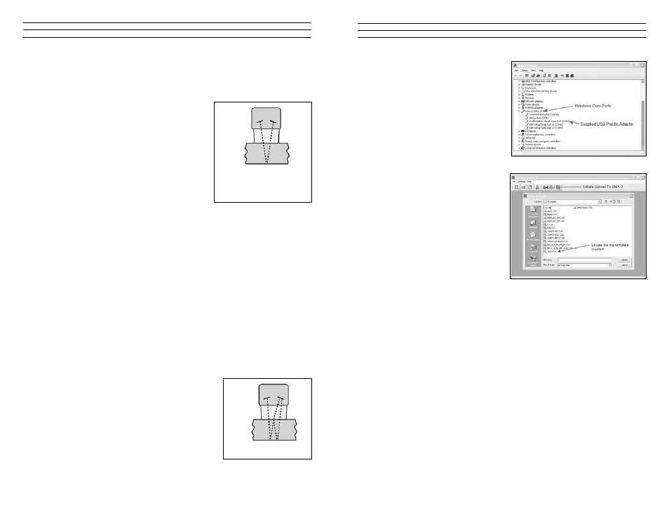
5. Click on SETTINGS, followed by
clicking on COM PORT, to view the
list of available ports. The default
setting for DataComm is always
AUTO. The AUTO mode searches
through all the possible com port
options, and looks for the port
‘automatically’.However,thiscan
take some time. Therefore, if the port
is already known,manually select the
port from the list.
noTe: A list of available ports can be
determined in the device manager of
the Windows® operating system.
6. Power on the TI-UMX2, and give it a
minute to fully boot up.
7. Click the UP ARROW icon to initiate
the file transfer. A dialog box will
appear, displaying the examples
folder created by DataComm on your
desktop. Alternatively, the upload
can be initiated from the menus
by clicking the FILE menu option,
followed by clicking the UPLOAD TO GAUGE option.
8. Select the file to be uploaded to the TI-UMX2.
9. Finally, click the UPLOAD button in the dialog box to start the transfer. A progress
bar will appear on the screen during the transfer process, and disappear once the
transfer has completed.
11.5 activating the data logger (TI-uMx2)
The following procedure explains the necessary steps to activate the data logger in the
TI-UMX2:
noTe: This section assumes the TI-UMX2 is powered up and ready to go. The
TI-UMX2 always boots up and displays the left most top level menu item, which
corresponds to the data logger. If anything, other than MEMOFF, is currently displayed,
the data logger is already active.
1. Press and hold the single TI-UMX2 button, located on the top end cap, until the top
level menu options begin scrolling on the alpha display. Once this occurs, the button
can now be released. The menu options will scroll one to the next in a time delayed
sequence, and will display all the menu options in a continuous loop.