Checkline TI-UMX2 User Manual
Page 11
– 11–
Zero: The TI-UMX2 can use two different types of transducers, a dual or single
element. This menu item will only be visible if the TI-UMX2 identified a dual element
transducer connected.
auTo
–TheautozerofeatureoftheTI-UMX2,performsan“offblock”electroniczero
automatically,eliminatingtheneedforamanualzeroonaspeciieddiskorblock.When
theTI-UMX2bootsup,itwillperformanautozeroduringthebootsequence.However,
anotherautozeromaybeneedtoaccountforchangesintemperature,oranincorrect
zeroduetocouplantontheendofthetransducerduringthezeroingprocess.Referto
section 7.2 for a detailed explanation.
Manual
–TheTI-UMX2isalsoequippedwithan“onblock”manualzerooption.
ThiszerowouldonlybeusedtoresettheinternalzeroforoftheTI-UMX2,asa
referencepointfortheautozero.Note:thereferencediskislocatedontheendofthe
TI-UMX2 enclosure. Refer to section 7.2 for a detailed explanation.
CoaTInG - In order to account for very slight electronic differences in transducers
of the same type, frequency, and diameter, the TI-UMX2 has been equipped with a
“zerocoating”feature.ThiszeroisonlyusedwhenthePECTcoatingmodefeatureis
being used. Although the coating thickness is not displayed on the TI-UMX2 actual
LCD displays, the coating thickness is stored with the base material thickness when
a measurement is saved to memory. Once the data is downloaded to a PC, the coating
thickness will be displayed with PECT measurement stored. Refer to section on 10.3 for
a detailed explanation.
GaIn: A 5 position gain switch in 2 db increments from 40 to 50 dB. Increase for better
penetration or punch, and decrease to eliminate unwanted noise or better resolution.
Refer to section 8.2 for further info.
– 46 –
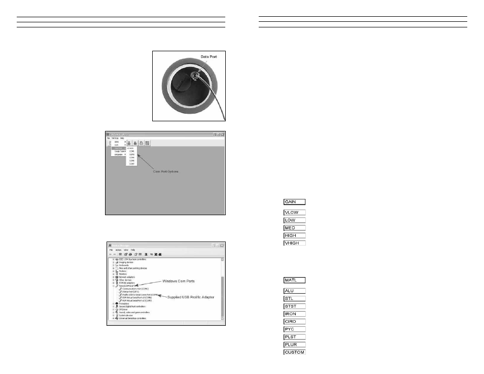
Uploading the Setup File
1. Remove the bottom end cap of the TI-UMX2, in
order to access the LEMO data jack. Remove the
rubber plug from the data jack.
2. Plug the LEMO connector into the data jack.
Note: align the red pin on the connector with
the data jack.
3. Plug either the RS232 into a serial port, or USB
connector into a USB port on the PC.
4. Start the DataComm utility software.
noTe: A list of available ports can be determined in the device manager of the
Windows® operating system.
5. Click on SETTINGS,
followed by clicking on
COM PORT, to view the
list of available ports.
The default setting for
DataComm is always
AUTO. The AUTO mode
searches through all the
possible com port options,
and looks for the port
‘automatically’.However,
this can take some time.
Therefore, if the port is
already known, manually
select the port from
the list.