2 electrical connections, 1 connections of the k-375, Electrical connections – BUCHI KjelSampler K-377 User Manual
Page 44: 5 .2 electrical connections, Notice
5 Putting into operation
44
K-375/376/377 Operation Manual, Version B
5 .2
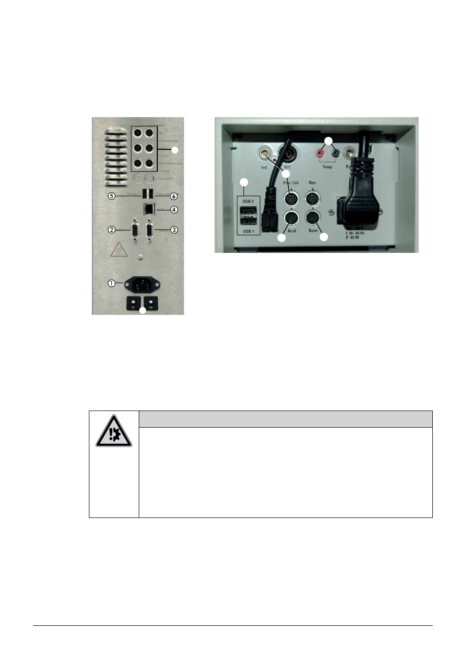
Electrical connections
5 .2 .1
Connections of the K-375
ቩ
ቨ
ቪ
ቫ
ቭ
ቮ
ቯ
a Power connection K-375
b RS232 connection to K-376/K-377
c RS232 connection to external bal-
ance
d LAN connection
e USB connection for external printer
f USB connection for bar code reader
g Connectors for level sensors
h Fuses (2 x 10A)
i Connector for dosing unit (Acid)
j Connector for additional dosing unit (Base)
k Additional USB-ports
l Connectors for colorimetric sensor (Ind. and Pwr. Col.) or pH electrode
(Ind. only)
m Connectors for temperature sensor
Fig. 5.1: Electrical connections of the K-375
NOTICE
Risk of device damage by wrong voltage.
• Make sure that the voltage on the socket corresponds to the voltage given on the type plate
of the instrument.
• Always connect the device to an earthed socket. External connections and extension cables
must be provided with an earthed conductor lead (3-pole couplings, cable or plug equipment)
as the mains lead has a molded plug, thus avoiding risks due to inadvertent defective wiring.
• Make sure that no electric sparks form in the device or its surroundings as they might
damage the instrument.
On the K-375 instrument
• Connect the power cable to the power connection
a
.
• Connect the level sensors to the corresponding connectors
g
.
NOTE
Unlike the level sensors for the storage tanks of H
2
0, NaOH and H
3
BO
3
, the presence of the level
sensors for the waste containers has to be indicated within the software! (See section “Peripherals”
in chapter 6.9.1)