BUCHI KjelSampler K-377 User Manual
Page 33
4 Description of function
33
K-375/376/377 Operation Manual, Version B
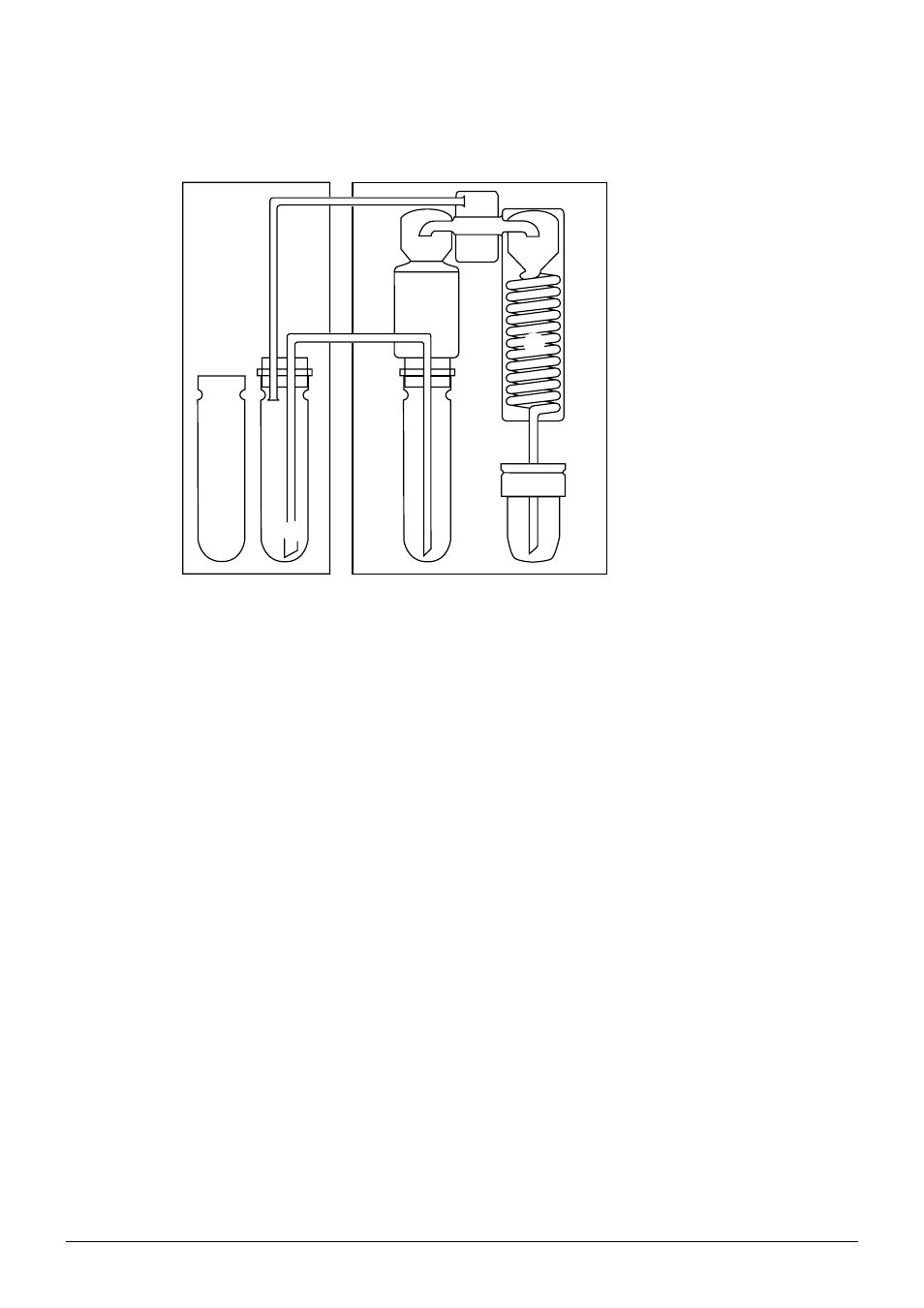
4 .2
Functional principle of Sampler System K-375 with K-376 or K-377
ቤ
ቢ
ባ
ቤ
ቦ
ቧ
ቨ
ቩ
ቪ
ብ
a K-376/K-377
b K-375
c Sample tube
d Dip tube
e Splash protector
f Steam generator
g Condenser
h Distillate outlet tube
i Receiving vessel
Fig. 4.3: Functional principle of the K-375 with K-376 or K-377
The sampler arm with dip tube is positioned in a sample tube in the K-376/K-377. The steam
generator of the K-375 generates steam which is lead into the sample tube in the K-376/K-377 via
the steam hose.
The steam presses the sample into the dip tube, so that the sample is transferred into the sample
tube in the K-375 via the transfer hose.
Water and sodium hydroxide is dosed into the sample tube in the K-375. Then steam is introduced
to drive out ammonia. The ammonia evaporates into the splash protector and condensates in the
condenser.
Boric acid is dosed into the receiving vessel, where the condensated ammonia is collected and finally
titrated.
During the entire distillation process, steam is transferred via the sample tube of the K-376/K-377 to
the sample tube of the K-375, thus ensuring a thorough cleaning of the sample tube and the transfer
hose.