2 function 1 group [fu1 – Cleveland Range inverter User Manual
Page 45
Chapter 4 - Parameter Description [FU1]
39
4.2 Function 1 Group [FU1]
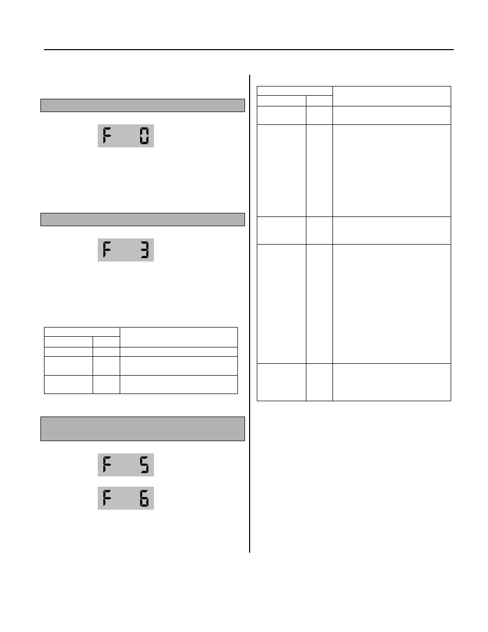
FU1-00: Jump to Desired Code #
Jumping directly to any parameter code can be
accomplished by entering the desired code
number.
FU1-03: Run Prevention
This function prevents reverse operation of the
motor. This function may be used for loads that
rotate only in one direction such as fans and
pumps.
Setting Range
Select Display
Description
None
0
Forward and reverse run is available.
Forward
Prevention
1
Forward run is prevented.
Reverse
Prevention
2
Reverse run is prevented.
FU1-05: Acceleration Pattern
FU1-06: Deceleration Pattern
Different combinations of acceleration and
deceleration patterns can be selected according
to your application.
Setting Range
Select Display
Description
Linear
0
This is a general pattern for constant
torque applications.
S-Curve
1
This pattern allows the motor to
accelerate and decelerate smoothly.
The actual acceleration and
deceleration time takes longer- about
40% than the time set in DRV-01 and
DRV-02.
This setting prevents shock during
acceleration and deceleration, and
prevents objects from swinging on
conveyors or other moving equipment.
U-Curve
2
This pattern provides more efficient
control of acceleration and deceleration
in typical winding machine applications.
Minimum
3
The inverter makes shorten the
acceleration time by accelerating with a
current rate of about 150% of its rated
current and reduces the deceleration
time by decelerating with a DC voltage
rate of 95% of its over-voltage trip level.
Appropriate application: When the
maximum capability of the inverter and
the motor are required.
Inappropriate application: The current
limit function may operate for a long
period of time for loads that have high
inertia such as fans.
Optimum
4
The inverter accelerates with a current
rate of about 120% of its rated current
and decelerates with a DC voltage rate
of 93% of its over-voltage trip level.
☞
Note: In case of selecting the ‘Minimum’ or ‘Optimum’, the
DRV-01 [Accel Time] and DRV-02 [Decel Time] is ignored.
☞
Note: ‘Minimum’ and ‘Optimum’ functions operate normally
when the load inertia is less than 10 times compared to the
motor inertia. (FU2-37)
☞
Note: ‘Optimum’ is useful when the motor capacity is smaller
than the inverter capacity.
☞
Note: ‘Minimum’ and ‘Optimum’ functions are not appropriate
for down operation in an elevator application.