BendixKing KMD 150 - Pilots Guide User Manual
Page 116
102
Rev 2 Oct/2002
KMD 150 Pilot's Guide
Once the physical connection to the host GPS or LORAN has been
made, it is essential to select an appropriate data output on the host unit.
This can be done by referring to the manual for the host GPS/LORAN
and choosing an option that corresponds to one of the compatible data
input types listed previously.
If the host GPS or LORAN is correctly connected, switched on and out-
putting data, the KMD 150 will automatically start to read and decode the
incoming data. There is no need to set an input type on the KMD 150 as
this is done automatically.
After a few seconds if data is being received, the word YES will appear
next to the RECEIVING DATA: heading. The type of data being
received will then be displayed beside the DATA INPUT: heading.
If the data being received contains valid fix information (i.e. the host GPS
has a fix) the word YES will appear next to the DATA VALID: heading.
Once the unit is receiving and validating the incoming data select PREV
PAGE and return to the MAIN MENU Screen.
OUTPUT TEST
If you are installing an
Internal GPS version of
the KMD 150 and have
made connection to other
avionics equipment on
the aircraft, screen 37
allows you to run some
installation tests. Screen
37 is accessed by
pressing Key 4 (OUTPUT
TEST) on Screen 35.
Once the tests are com-
plete, return to screen 35
by pressing key 1 (PREV PAGE).
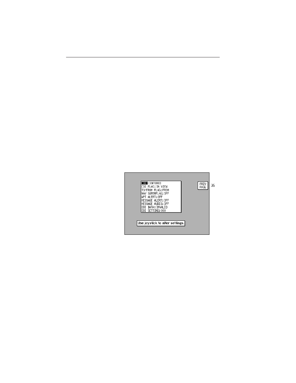
The following flags and commands can be functioned from the OUTPUT
TEST screen:
CDI
Full Scale (FSD) Left
Ensure CDI is deflected full scale left (5
dots)
Full Scale (FSD) Right Ensure CDI is deflected full scale right (5
dots)
Centered
Ensure that the CDI is centered
Setup Screens
Screen 37: Aviation Interface Output Test
Screen