Carrier 17EX User Manual
Page 88
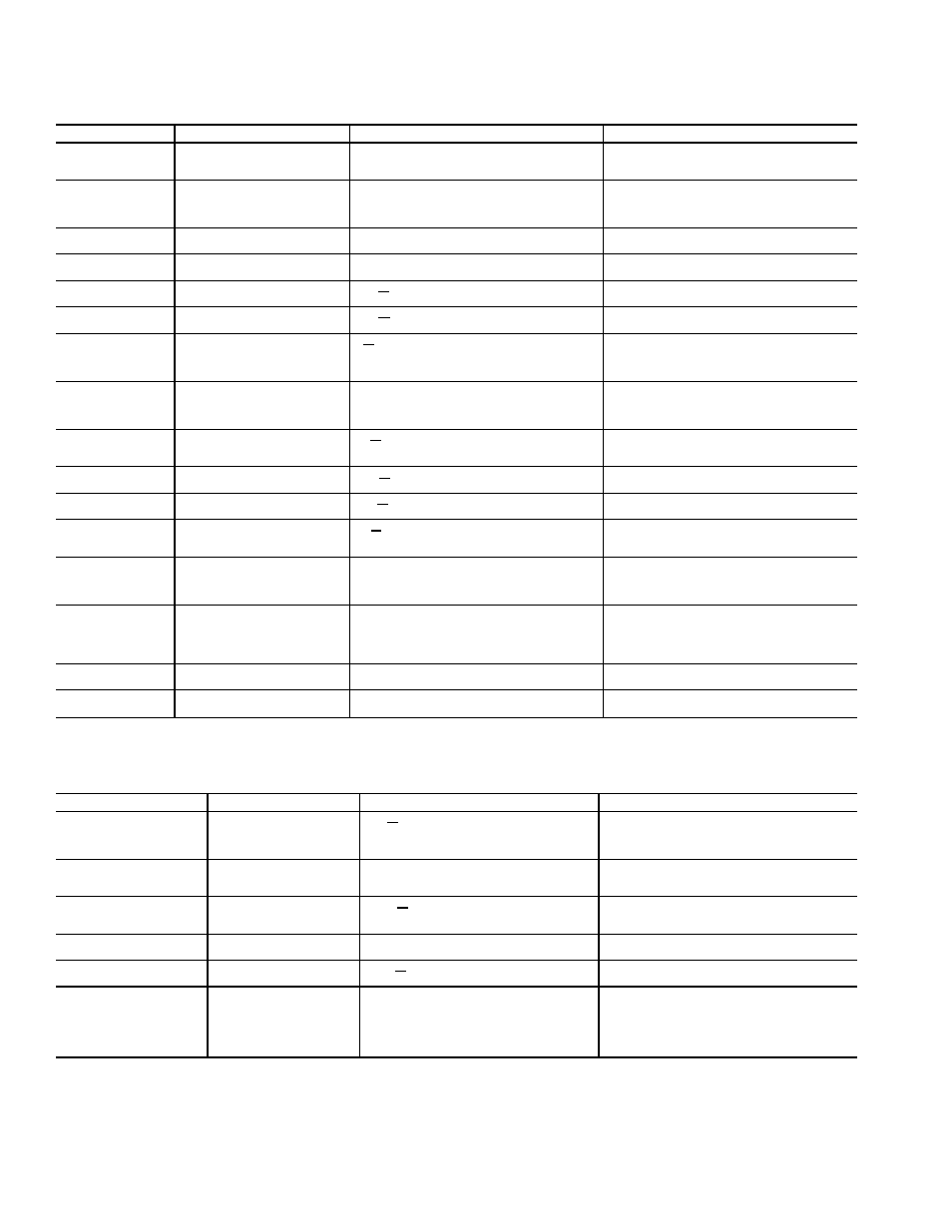
Table 12 — LID Primary and Secondary Messages and Custom Alarm/Alert Messages
with Troubleshooting Guides (cont)
G. START-UP FAILURES: This is an alarm condition. A manual reset is required to clear.
PRIMARY MESSAGE
SECONDARY MESSAGE
ALARM MESSAGE/PRIMARY CAUSE
ADDITIONAL CAUSE/REMEDY
FAILURE TO START
LOW OIL PRESSURE
OILPD [VALUE] exceeded limit of [LIMIT]*. Check
oil pump system.
Check for closed oil supply valves. Check oil filter.
Check for low oil temperature. Check transducer
accuracy.
FAILURE TO START
OIL PRESS SENSOR FAULT
OILPD [VALUE] exceeded limit of [LIMIT]*. Check
oil pressure sensor.
Check for excessive refrigerant in oil sump. Run oil
pump manually for 5 minutes. Check calibration of
oil pressure differential amplifier modules. Check wir-
ing. Replace transducers if necessary.
FAILURE TO START
LOW CHILLED WATER FLOW
EVFL Evap Flow Fault: Check water pump/flow
switch.
Check wiring to flow switch. Check through CON-
TROL TEST for proper switch operation.
FAILURE TO START
LOW CONDENSER
WATER FLOW
CDFL Cond. Flow Fault: Check water pump/flow
switch.
Check wiring to flow switch. Check through CON-
TROL TEST for proper switch operation.
FAILURE TO START
STARTER FAULT
STR
FLT Starter Fault: Check Starter for Fault
Source.
A starter protective device has faulted. Check starter
for ground fault, voltage trip, temperature trip, etc.
FAILURE TO START
STARTER OVERLOAD TRIP
STR
FLT Starter Overload Trip: Check amps
calibration/reset overload.
Reset overloads, check ICR relay before restarting
chiller.
FAILURE TO START
LINE VOLTAGE DROPOUT
V
P Single-Cycle Dropout Detected: Check volt-
age supply.
Check voltage supply. Check transformers for sup-
ply. Check with utility if voltage supply is erratic. Moni-
tor must be installed to confirm consistent, single-
cycle dropouts. Check low oil pressure switch.
FAILURE TO START
HIGH CONDENSER
PRESSURE
High Condenser Pressure [LIMIT]:* Check switch
2C aux, and water temperature/flow.
Check for proper design condenser flow and tem-
perature. Check condenser approach. Check 2C aux-
iliary contacts on oil sump starter. Check high pres-
sure switch.
FAILURE TO START
EXCESS ACCELERATION
TIME
CA
P Excess Acceleration: Check guide vane clo-
sure at start-up.
Check that guide vanes are closed at start-up. Check
starter for proper operation. Reduce unit pressure
if possible.
FAILURE TO START
STARTER TRANSITION
FAULT
RUN
AUX Starter Transition Fault: Check 1CR/
1M/Interlock mechanism.
Check starter for proper operation.
Run contact failed to close.
FAILURE TO START
1CR AUX CONTACT FAULT
1CR
AUX Starter Contact Fault: Check 1CR/1M
aux. contacts.
Check starter for proper operation.
Start contact failed to close.
FAILURE TO START
MOTOR AMPS NOT SENSED
CA
P Motor Amps Not Sensed: Check motor load
signal.
Check for proper motor amps signal to SMM. Check
wiring from SMM to current transformer. Check main
motor circuit breaker for trip.
FAILURE TO START
CHECK REFRIGERANT TYPE
Current Refrigerant Properties Abnormal — Check
Selection of refrigerant type.
Pressures at transducers indicate another refriger-
ant type in control test. Make sure to access the AT-
TACH TO NETWORK DEVICE screen after speci-
fying HFC-134a refrigerant type.
FAILURE TO START
LOW OIL PRESSURE
Low Oil Pressure [LIMIT]:* Check oil pressure switch/
pump and 2C aux.
The oil pressure differential switch is open when the
compressor tried to start. Check the switch for proper
operation. Also, check the oil pump interlock (2C aux)
in the power panel and the high condenser pres-
sure switch.
FAILURE TO START
LOW GEAR OIL PRESSURE
GEAROILP [VALUE] exceeded limit of [LIMIT].*
Check gear oil pump/filter.
Check for closed oil supply valves. Check oil filter.
Check transducer accuracy.
FAILURE TO START
GEAR OIL PRESSURE SENSOR
Gear Oil Pressure Transducer Out of Range [VALUE].
Check calibration of transducer. Replace if
necessary.
*[LIMIT] is shown on the LID as the temperature, pressure, voltage, etc., set point predefined or selected by the operator as an override, alert, or alarm condition. [VALUE]
is the actual pressure, temperature, voltage, etc., at which the control tripped.
H. COMPRESSOR JUMPSTART AND REFRIGERANT PROTECTION
PRIMARY MESSAGE
SECONDARY MESSAGE
ALARM MESSAGE/PRIMARY CAUSE
ADDITIONAL CAUSE/REMEDY
UNAUTHORIZED
OPERATION
UNIT SHOULD BE
STOPPED
CA
P Emergency: Compressor
running without control authorization.
Compressor is running with more than 10% RLA
and control is trying to shut it down. Turn power
off to compressor if unable to stop. Determine cause
before re-powering.
POTENTIAL FREEZE-UP
EVAP PRESS/TEMP
TOO LOW
ERT Emergency: Freeze-up
prevention.
Determine cause. If pumping refrigerant out of
chiller, stop operation and go over pumpout
procedures.
FAILURE TO STOP
DISCONNECT POWER
RUN
AUX Emergency: DISCONNECT
POWER.
Starter run and start contacts are energized while
control tried to shut down. Disconnect power to
starter.
LOSS OF
COMMUNICATION
WITH STARTER
Loss of Communication with Starter: Check
chiller.
Check wiring from PSIO to SMM. Check SMM mod-
ule troubleshooting procedures.
STARTER CONTACT
FAULT
ABNORMAL 1CR OR
RUN AUX
1CR
AUX Starter Contact Fault: Check
1CR/1M aux. contacts.
Starter run and start contacts energized while chiller
was off. Disconnect power.
POTENTIAL FREEZE UP
COND PRESS/TEMP
TOO LOW
CRT [VALUE] exceeded limit of [LIMIT]*
Emergency: Freeze-up prevention.
The condenser pressure transducer is reading a
pressure that could freeze the water in the con-
denser tubes. Check for condenser refrigerant leaks,
bad transducers, or transferred refrigerant. Place
the unit in PUMPDOWN mode to eliminate the
alarm if vessel is evacuated.
*[LIMIT] is shown on the LID as the temperature, pressure, voltage, etc., set point predefined or selected by the operator as an override, alert, or alarm condition. [VALUE]
is the actual pressure, temperature, voltage, etc., at which the control tripped.
88