Carrier 17EX User Manual
Page 23
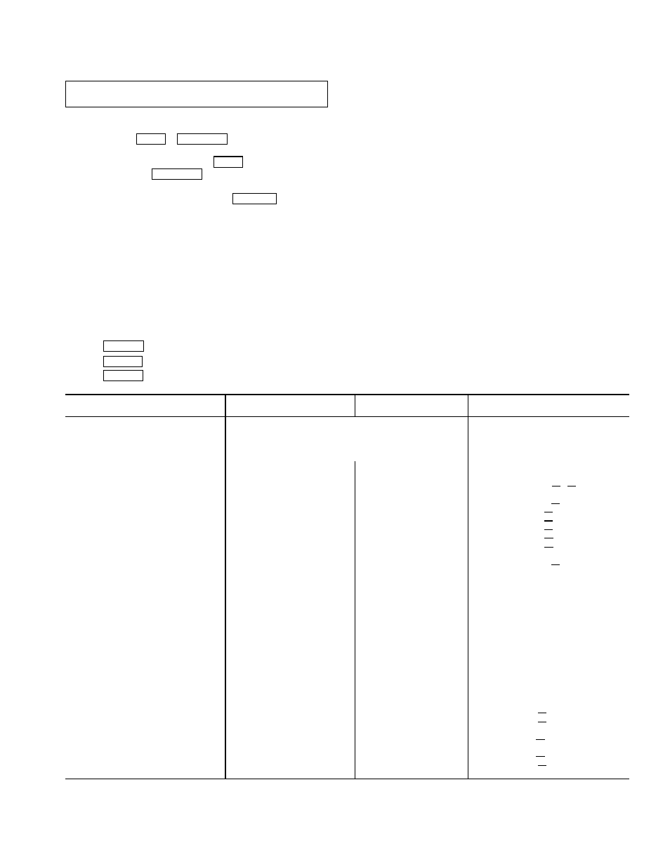
Table 2 — LID Display Data
NOTES:
IMPORTANT: The following notes apply to all Table 2
examples.
1. Only 12 lines of information appear on the LID screen at any one
time. Press the NEXT or PREVIOUS softkey to highlight a point
or to view items below or above the current screen. If you have a
chiller with a backlit LID, press the NEXT softkey twice to page
forward; press the PREVIOUS softkey twice to page back.
2. To access the information shown in Examples 6 through 14, enter
your 4-digit password after pressing the SERVICE softkey. If no
softkeys are pressed for 15 minutes, the LID automatically logs off
(to prevent unrestricted access to PIC controls) and reverts to the
default screen. If this happens, you must reenter your password
to access the tables shown in Examples 6 through 14.
3. Terms in the Description column of these tables are listed as they
appear on the LID screen.
4. The LID may be configured in English or Metric (SI) units using
the LID CONFIGURATION screen. See the Service Operation sec-
tion, page 42, for instructions on making this change.
5. The items in the Reference Point Name column
do not appear on
the LID screen. They are data or variable names used in CCN or
Building Supervisor software. They are listed in these tables as a
convenience to the operator if it is necessary to cross reference
CCN/BS documentation or use CCN/BS programs. For more in-
formation, see the 17EX CCN literature.
6. Reference Point Names shown in these tables in all capital letters
can be read by CCN and Building Supervisor software. Of these
capitalized names, those preceded by an asterisk can also be
changed (that is, written to) by the CCN, Building Supervisor soft-
ware and the LID. Capitalized Reference Point Names preceded
by two asterisks can be changed only from the LID. Reference
Point Names in lower case type can be viewed by CCN or Build-
ing Supervisor software only by viewing the whole table.
7. Alarms and Alerts: An asterisk
in the far right field of a LID status
screen indicates that the chiller is in an alarm state; an exclama-
tion point in the far right field of the LID screen indicates an alert
state. The asterisk (or exclamation point) indicates that the value
on that line has exceeded (or is approaching) a limit. For more
information on alarms and alerts, see the Alarms and Alerts sec-
tion, page 16.
EXAMPLE 1 — STATUS01 DISPLAY SCREEN
To access this display from the LID default screen:
1. Press
MENU
.
2. Press STATUS (STATUS01 will be highlighted).
3. Press SELECT .
DESCRIPTION
RANGE
UNITS
REFERENCE POINT NAME
(ALARM HISTORY)
Control Mode
Reset.Off. Local. CCN
MODE
Run Status
Timeout. Recycle. Startup.
STATUS
Ramping. Running. Demand.
Override. Shutdown. Abnormal.
Pumpdown
Occupied ?
No/Yes
OCC
Alarm State
Normal/Alarm
ALM
*Chiller Start/Stop
Stop/Start
CHIL
S
S
Base Demand Limit
40-100
%
DLM
*Active Demand Limit
40-100
%
DEM
LIM
Compressor Motor Load
0-999
%
CA
L
Current
0-999
%
CA
P
Amps
0-9999
AMPS
CA
A
*Target Guide Vane Pos
0-100
%
GV
TRG
Actual Guide Vane Pos
0-100
%
GV
ACT
Water/Brine: Setpoint
10-120 (–12.2-48.9)
DEG F (DEG C)
SP
*
Control Point
10-120 (–12.2-48.9)
DEG F (DEG C)
LCW
STPT
Entering Chilled Water
–40-245 (–40-118)
DEG F (DEG C)
ECW
Leaving Chilled Water
–40-245 (–40-118)
DEG F (DEG C)
LCW
Entering Condenser Water
–40-245 (–40-118)
DEG F (DEG C)
ECDW
Leaving Condenser Water
–40-245 (–40-118)
DEG F (DEG C)
LCDW
Evaporator Refrig Temp
–40-245 (–40-118)
DEG F (DEG C)
ERT
Evaporator Pressure
–6.7-420 (–46-2896)
PSI (kPa)
ERP
Condenser Refrig Temp
–40-245 (–40-118)
DEG F (DEG C)
CRT
Condenser Pressure
–6.7-420 (–46-2896)
PSI (kPa)
CRP
Discharge Temperature
–40-245 (–40-118)
DEG F (DEG C)
CMPD
Bearing Temperature
–40-245 (–40-118)
DEG F (DEG C)
MTRB
Motor Winding Temp†
–40-245 (–40-118)
DEG F (DEG C)
MTRW
Motor Winding Hi
Temp Cutout
Normal/Alarm
MTRW
Oil Sump Temperature
–40-245 (–40-118)
DEG F (DEG C)
OILT
Oil Pressure Transducer†
–6.7-420 (–46-2896)
PSI (kPa)
OILP
Oil Pressure**
–6.7-420 (–46-2896)
PSID (kPad)
OILPD
Line Voltage:
Percent
0-999
%
V
P
Actual
0-9999
VOLTS
V
A
*Remote Contacts Input
Off/On
REMCON
Total Compressor Starts
0-65535
c
starts
Starts in 12 Hours
0-8
STARTS
Compressor Ontime
0-500000.0
HOURS
c
hrs
*Service Ontime
0-32767
HOURS
S
HRS
*Compressor Motor kW
0-9999
kW
CKW
†Information is applicable to hermetic chillers (19EX) only.
**Oil pressure is read directly from a differential pressure module on 17EX chillers.
NOTE: values preceded by an asterisk (*) can be forced (changed by an operator) from the LID screen
or from another control device (such as a Carrier Comfort Network [CCN] terminal).
23