Carrier 17EX User Manual
Page 106
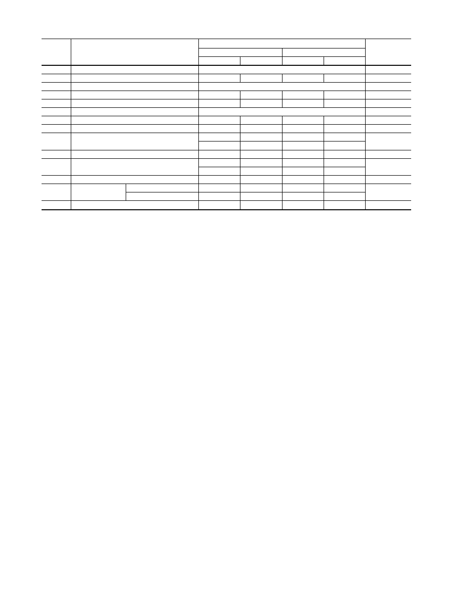
Table 26 — Compressor Fits and Clearances
ITEM
DESCRIPTION
CLEARANCE
TYPE OF
MEASURE
Minimum
Maximum
in.
mm
in.
mm
1
1st Stage Impeller to Diaphragm
See Tabulation
Axial
2
Interstage Labyrinth
0.012
0.305
0.016
0.406
Diametral
3
2nd Stage Impeller to Discharge Wall
See Tabulation
Axial
4
Thrust End Journal Bearing
0.0035
0.0889
0.0055
0.1397
Diametral
5
Thrust End Float
0.010
0.254
0.015
0.381
Axial
6
Inner Carbon Ring Travel
.06 in. (1.52 mm) minimum in each direction
Axial
7
Shaft End Labyrinth
0.001
0.025
0.005
0.127
Diametral
8
Windage Baffle to Shaft
0.092
2.337
0.095
2.413
Diametral
9
Shaft Displacement (Shrouds 3 - 6)
Detector (Shrouds 8 & 9)
0.008
0.203
0.010
0.254
Axial
0.023
0.584
0.025
0.635
10
Counterthrust Bearing Seal Ring
0.006
0.152
0.010
0.254
Diametral
11
Balancing Piston, Labyrinth
0.008
0.203
0.012
0.305
Diametral
0.018
0.457
0.022
0.559
12
2nd Stage Labyrinth
0.008
0.203
0.012
0.305
Diametral
13
1st Stage
Labyrinth
(Shrouds 3 - 6)
0.016
0.406
0.020
0.508
Diametral
(Shrouds 8 & 9)
0.018
0.457
0.022
0.559
14
Seal End Journal Bearing
0.0035
0.0889
0.0055
0.1397
Diametral
106