Carrier 17EX User Manual
Page 11
CONTROLS
Definitions
ANALOG SIGNAL — An analog signal varies in propor-
tion to the monitored source. It quantifies values between
operating limits. (Example: A temperature sensor is an ana-
log device because its resistance changes in proportion to
the temperature, generating many values.)
DIGITAL SIGNAL — A digital (discrete) signal is a 2-position
representation of the value of a monitored source.
(Example: A switch is a digital device because it only in-
dicates whether a value is above or below a set point or bound-
ary by generating an on/off, high/low, or open/closed signal.)
VOLATILE MEMORY — Volatile memory is memory in-
capable of being sustained if power is lost and subsequently
restored.
The memories of the PSIO and LID modules are vola-
tile. If the battery in a module is removed or damaged,
all programming will be lost.
General —
The 17EX externally geared open-drive cen-
trifugal liquid chiller contains a microprocessor-based con-
trol center that monitors and controls all operations of the
chiller. The microprocessor control system matches the cool-
ing capacity of the chiller to the cooling load while provid-
ing state-of-the-art chiller protection. The system controls
cooling load within the set point plus the deadband by sens-
ing the leaving chilled water or brine temperature and regu-
lating the inlet guide vane via a mechanically linked actua-
tor motor. The guide vane is a variable flow prewhirl assembly
that controls the refrigeration effect in the cooler by regu-
lating the amount of refrigerant vapor flow into the com-
pressor. An increase in guide vane opening increases capac-
ity. A decrease in guide vane opening decreases capacity. Chiller
protection is provided by the processor which monitors the
digital and analog inputs and executes capacity overrides or
safety shutdowns, if required.
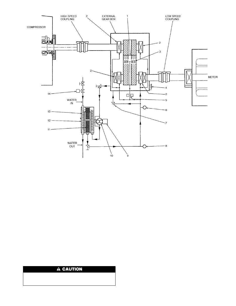
1 — Gear Mesh
2 — Bearings
3 — Gear Mesh Spray
4 — Oil Level Glass
5 — Orifice
6 — Oil Supply Pressure
Transducer
7 — Pressure Control Valve
8 — Oil Supply Temperature Thermistor
9 — Oil Pump Motor
10 — Oil Pump and Pressure Regulator
11 — Oil Filter
12 — Oil Cooler/Filter
13 — Oil Cooler
14 — Plug Valve
NOTE: The oil reservoir is at the base of the gear box.
Fig. 5 — External Gear Oil Lubrication Cycle (Plan View)
11