Rear view, Internal storage device, Fig. 24: rear side of the medi client iia system – Kontron Medi Client IIA 104 (EOL) User Manual
Page 32
7. Product Description
Medi Client IIA - Instructions for use (Version 1.03)
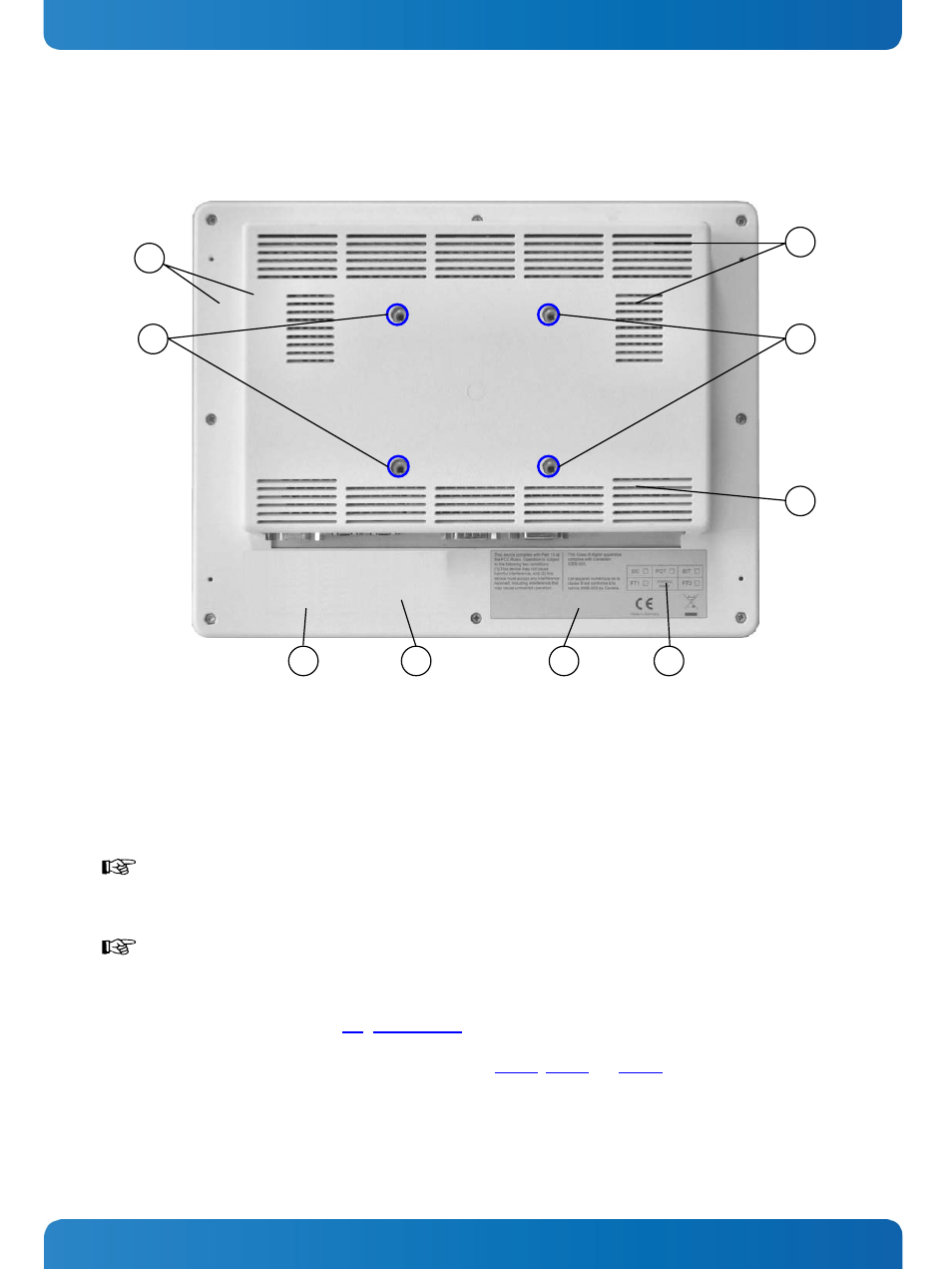
7.4. Rear View
2
2
4
3
1
Fig. 24: Rear side of the Medi Client IIA system
8
7
6
5
1 Rear part of the display/system enclosure
2 4x threaded holes (marked blue in the picture) for
mounting on VESA
®
75 compliant mounting system
3 Air intake openings
4 Air exhaust openings
5 Location for type label of the system
6 Location for label for medical devices
7 FCC verification label
8 Inspection status label
When powering on the Medi Client IIA system, make sure that the air intake and exhaust openings are
not obstructed.
Medi Client IIA 104 is VESA
®
75 compliant and the Medi Client IIA 150 is VESA
®
75/100 compliant
Use four M4 metric screws to attach the system to a VESA
®
mounting system. Depending on the
VESA
®
mounting system used, choose the length of the screws so that the screw-in depth of the screws
should be between 4mm (0.16") up to 7mm (0.28"). For corresponding screws refer to the screw type
included in the chapter 6.1 “Optional Parts”.
Using longer screws could damage the internal components of the Medi Client IIA system.
For VESA
®
mounting details, please observe the Fig. 31, Fig. 32 and Fig. 34.
7.5. Internal Storage Device
The system can be optionally equipped with a CF card, type I and/or an internal 2.5" HDD (SATA).
30
www.kontron.com