Bottom view, Power and reset, Fig. 12: bottom view – Kontron Medi Client IIA 104 (EOL) User Manual
Page 25: Fig. 13: detail of the bottom side with interfaces, Fig. 13
7. Product Description
Medi Client IIA - Instructions for use (Version 1.03)
7.2. Bottom View
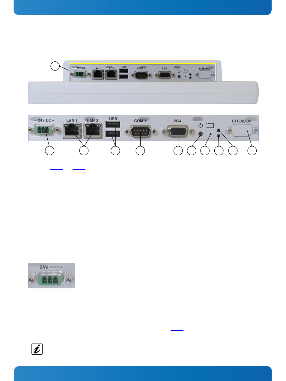
Fig. 12: Bottom view
Fig. 13: Detail of the bottom side with interfaces
Legend for Fig. 12 and Fig. 13:
1 Power, controls and interfaces on the bottom side
2 DC power connector (24VDC)
3 2x Ethernet (10/100/1000 Mbps) interface connector
4 2x USB (2.0) connector
5 COM1 serial port connector (RS232)
6 VGA interface connector
7 Power button
8 Reset button
9 HDD LED
10 Power LED
11 Knock out for additional interfaces
7.2.1. Power and Reset
7.2.1.1.
DC In Power Connector
Fig. 14: DC Power connector on the bottom
(rear) side of the Medi Client IIA system
1
2
5
3
7
6
4
8
9
10
11
The DC In power connector (refer to Fig. 13, pos. 2 and Fig. 14)
provides the power connection of the
Medi Client IIA system to
the main power source via the DC power cable (optional
accessory) or via the AC/DC adapter (optional accessory). For the
pin assignment refer to the section 10.1.1 “Power Connector.
7.2.1.2.
Reset Button
To restart the system, e.g. after a system hang-up, press the RESET button (Fig. 13, pos. 8). The system restarts
automatically without turning the computer off and on again.
During a reset all data in the main memory will be erased.
www.kontron.com
23