Storage drive activity led, Interfaces (rear, bottom side of the system), Fig. 19 mounted to the serial interface of – Kontron Medi Client IIA 104 (EOL) User Manual
Page 27
7. Product Description
Medi Client IIA - Instructions for use (Version 1.03)
7.2.4. Storage Drive Activity LED
Refer to (Fig. 13, pos. 9) for the storage drive activity LED location. Depending on the system configuration [a CF card,
type I and/or an internal 2.5" HDD (SATA)] and storage drive/s activity this LED may be blinking as shown below:
Fig. 18: Color of the storage drive activity LED, depending on the system configuration
7.2.5. Interfaces (Rear, Bottom Side of the System)
7.2.5.1.
Ethernet Interface Connectors
These interface connectors (refer to Fig. 13, pos.3) are provided as RJ45 sockets with integrated LEDs and support a
10/100/1000 Mbps data transfer rate.
Ethernet LED States:
Left LED State
Link Activity State
Right LED State
Link Speed
off
Link not active
Off
10 Base-T
green Link
active
green 100
Base-T
green
Link active
orange
1000 base-T
7.2.5.2.
USB interface Connectors
The system is equipped at the bottom side (rear) with two USB 2.0 interface connectors (refer to Fig. 13, pos. 4). These
connectors provide connections for USB-compatible devices.
7.2.5.3.
Serial Interface Connector
This RS232 connection (refer to Fig. 13, pos. 5) is available as 9-pin D-SUB connectors (male) and provides connection
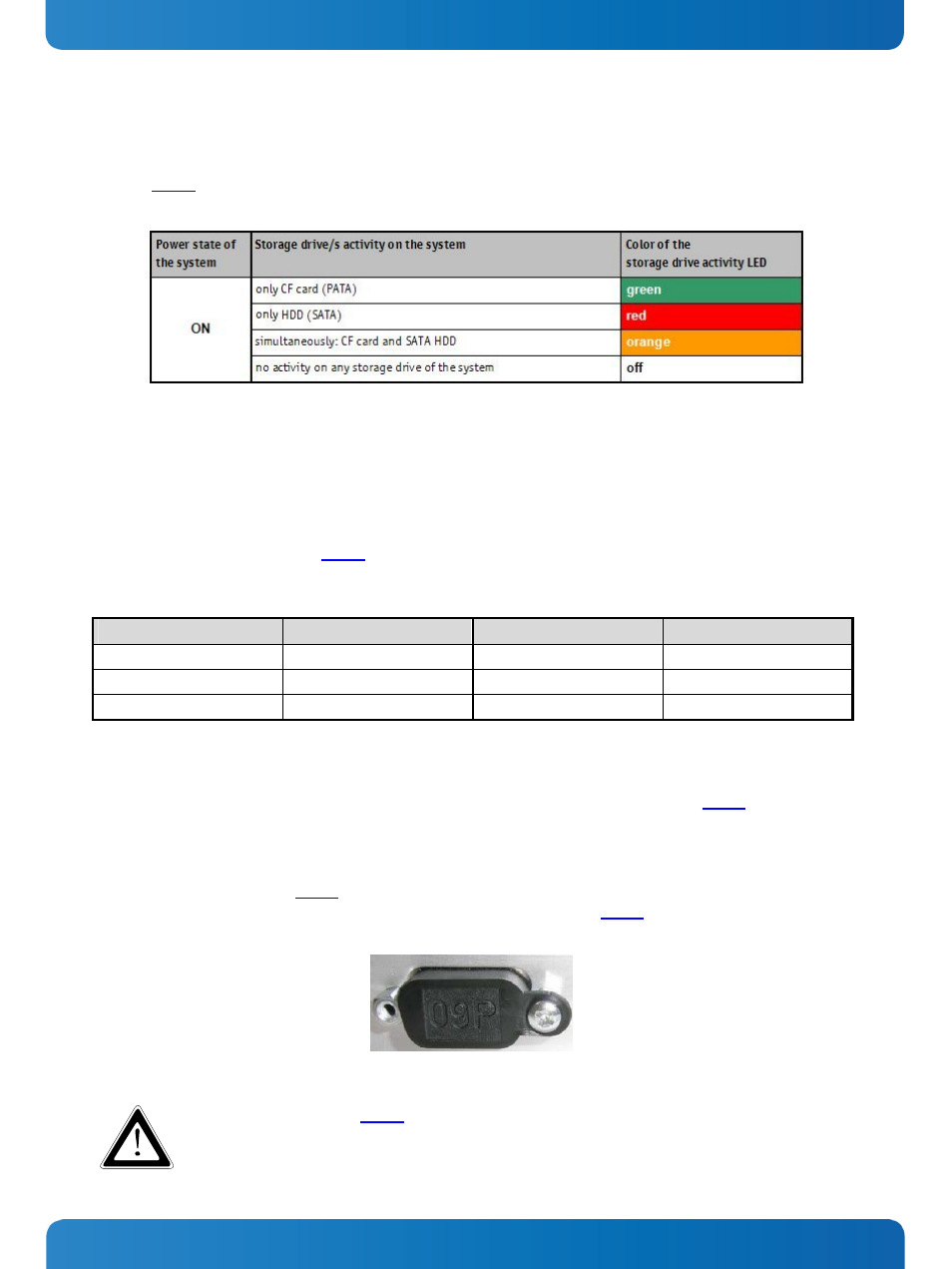
(RS232) for serial devices. The system is delivered with an ESD protection cover (Fig. 19) mounted to this serial interface
in order to ensure the ESD protection if no serial device is connected to this port.
Fig. 19: ESD protection cover for the male serial port
The ESD protection cover (Fig. 19) should be removed only when a serial device will be connected to
the serial port.
www.kontron.com
25