Power button on the interface side, Power led on the interface side and error codes, Fig. 15: color code for current system power state – Kontron Medi Client IIA 104 (EOL) User Manual
Page 26: Fig. 16:example of eerror codes, Fig. 17: errors priority
7. Product Description
Medi Client IIA - Instructions for use (Version 1.03)
7.2.2. Power Button on the Interface Side
The power button (Fig. 13, pos. 7) allows to power ON/OFF the system. Please observe the settings in BIOS Setup /
Chipset Configuration / South Bridge Configuration / Restore on AC Power Loss with option settings:
Power on (default)/
Power off).
Please observe the description in the section 8.2 ”System Self Protection against Ambient Overheating”. The power
button is deactivated as long as the protection against overheating function is active.
Even when the system is turned off via the power button there is still a standby-voltage of 5 V on the
SBC. The system is not completely disconnected from the main power supply by turning off via the
power button.
Hints for DC power connection:
The DC main power supply should be able to be switched off and on via a 2-pole isolating switch.
The unit is only completely disconnected from the DC main power supply, when the DC power cord is
disconnected either from the DC main or the unit. Therefore, the DC power cord and its connectors
must always remain easily accessible.
Hints for AC power connection via the optional external AC/DC adapter:
If the Medi Client IIA system is connected to an AC power source via an AC/DC adapter, the main power
cable of the external AC/DC adapter serves as disconnecting device. For this reason the outlet of the
AC power source must be located near to the device and be easily accessible.
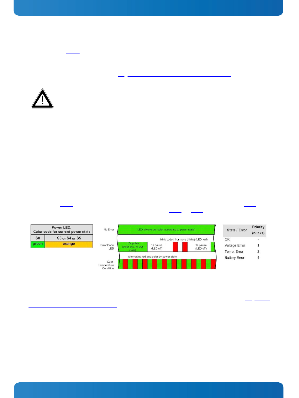
7.2.3. Power LED on the Interface Side and Error Codes
The power LED (Fig. 13, pos. 10) indicates the current system power state (S0, S3, S4, or S5) as shown in the
power LED will blink red if an error condition was detected; refer to the
. The blink code is independent
from the systems power states LED color. The color red is reserved for error codes, only.
Fig. 15: Color code for current system
power state
Fig. 16:Example of eError codes
Fig. 17: Errors priority
An over-temperature condition has the highest of all priorities. Please observe the description in the chapter 8.2 “System
Self Protection against Ambient Overheating”. The power button is deactivated as long as the temperature is too high.
To signalize this emergency state, the LED alternates between red and the current power state color.
Note: Higher priority codes will not interrupt a code which has started until the current blink code is completed.
24
www.kontron.com