Table 3-37: 0x290: led configuration register, Table 3-38: 0x291: led control register – Kontron COMe-cP2020 User Manual
Page 57
www.kontron.com
COMe-P2020 User Guide
57
•
POST Mode: LEDs build a binary vector to display POST code during the pre-boot phase. In doing so, the higher 4-bit
nibble of the 8-bit POST code is displayed followed by the lower nibble followed by a pause.
•
Mode A: LEDs controlled by CPU
Beside the configurable functions described above the LEDs fulfill also a basic debug function during the power up phase as
long as the first access to POST Code LOW Byte Register (0x080) is processed. If a LED lights red and stays red, then a basic
error is present on the board.
The following debug functions are defined and displayed during this initialization phase:
•
LED3: PGOOD failure, Power Good status not reached
•
LED2: not used
•
LED1: CPU reset is asserted/not asserted
•
LED0: U-Boot boot failure
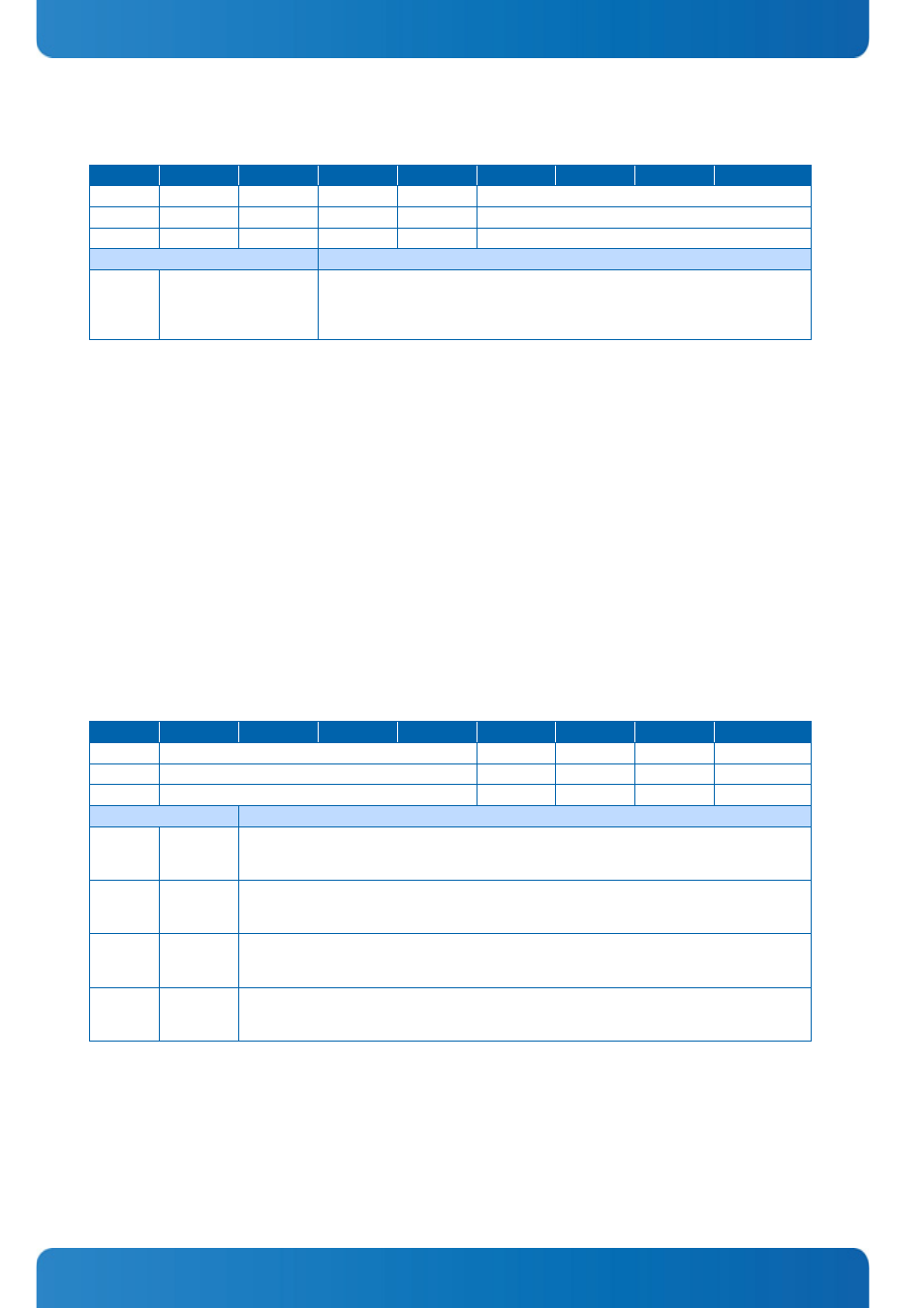
Table 3-37:
0x290: LED Configuration Register
ACTION
D7
D6
D5
D4
D3
D2
D1
D0
READ
0
0
0
0
LCON
WRITE
NU
NU
NU
NU
LCON
POWER UP
0
0
0
0
0000
BITFIELD
DESCRIPTION
[D0-D3]
LCON
Use specif ic LED conf iguration:
"0000" = POST
"0001" = Mode A (General Purpose Mode)
others = Reserved
Table 3-38:
0x291: LED Control Register
ACTION
D7
D6
D5
D4
D3
D2
D1
D0
READ
0000
LED3
LED2
LED1
LED0
WRITE
NU
LED3
LED2
LED1
LED0
POWER UP
0000
0
0
0
0
BITFIELD
DESCRIPTION
[D0]
LED0
LED Control Register, controls Board LED D5:
'0' = LED is OFF
'1' = LED is ON
[D1]
LED1
LED Control Register, controls Board LED D6:
'0' = LED is OFF
'1' = LED is ON
[D2]
LED2
LED Control Register, controls Board LED D7:
'0' = LED is OFF
'1' = LED is ON
[D3]
LED3
LED Control Register, controls Board LED D3:
'0' = LED is OFF
'1' = LED is ON