Table 3-35: 0x28c: watchdog timer register, Table 3-36: 0x28d: board id low byte register, Table 3-35 – Kontron COMe-cP2020 User Manual
Page 56: Table 3-36
www.kontron.com
COMe-P2020 User Guide
56
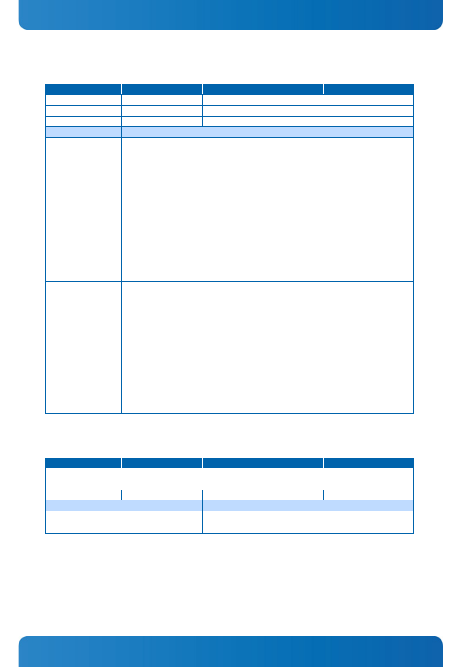
Table 3-35:
0x28C: Watchdog Timer Register
ACTION
D7
D6
D5
D4
D3
D2
D1
D0
READ
WTE
WMD
WEN/WTR
WTM
WRITE
w1c
WMD
WEN/WTR
WTM
POWER UP
0
00
0
0000
BITFIELD
DESCRIPTION
[D0-D3]
WTM
Watchdog timeout settings:
"0000" = 0.125 s
"0001" = 0.25 s
"0010" = 0.5 s
"0011" = 1 s
"0100" = 2 s
"0101" = 4 s
"0110" = 8 s
"0111" = 16 s
"1000" = 32 s
"1001" = 64 s
"1010" = 128 s
"1011" = 256 s
"1100" = 512 s
"1101" = 1024 s
"1110" = 2048 s
"1111" = 4096 s
[D4]
WEN/WTR
Watchdog timer enable/watchdog trigger:
'0' = Watchdog timer not enabled. Prior to the Watchdog being enabled, this bit is known as
WEN. After the Watchdog is enabled, it is known as WTR. Once the Watchdog timer has been
enabled, this bit cannot be reset to 0. As long as the Watchdog timer is enabled, it will indicate a
'1'.
'1' = Watchdog timer enabled. Writing a '1' to this bit causes the Watchdog to be retriggered to
the timer value indicated by bits WTM[3:0]
[D5-D6]
WMD
Watchdog mode:
"00" = Timer only mode
"01" = Reset mode
"10" = Interrupt mode
"11" = Cascaded mode (dual-stage)
[D7]
WTE
Watchdog timer expired status bit, writing '1' clears the bit:
'0' = Watchdog timer has not expired
'1' = Watchdog timer has expired
Table 3-36:
0x28D: Board ID Low Byte Register
ACTION
D7
D6
D5
D4
D3
D2
D1
D0
READ
Board-Register-Low-Byte[7:0]
WRITE
Board-Register-Low-Byte[7:0]
POWER UP
0
1
0
0
1
0
0
0
BITFIELD
DESCRIPTION
[D0-D7]
Board-Register-Low-Byte[7:0]
Board Identif ication Low Byte:
COMe_P2020: 0xD048