3 jtag/debug interface, Figure 2-1: irq routing scheme, Carrier come_cp2020 – Kontron COMe-cP2020 User Manual
Page 36
www.kontron.com
COMe-P2020 User Guide
36
2.5.2.11
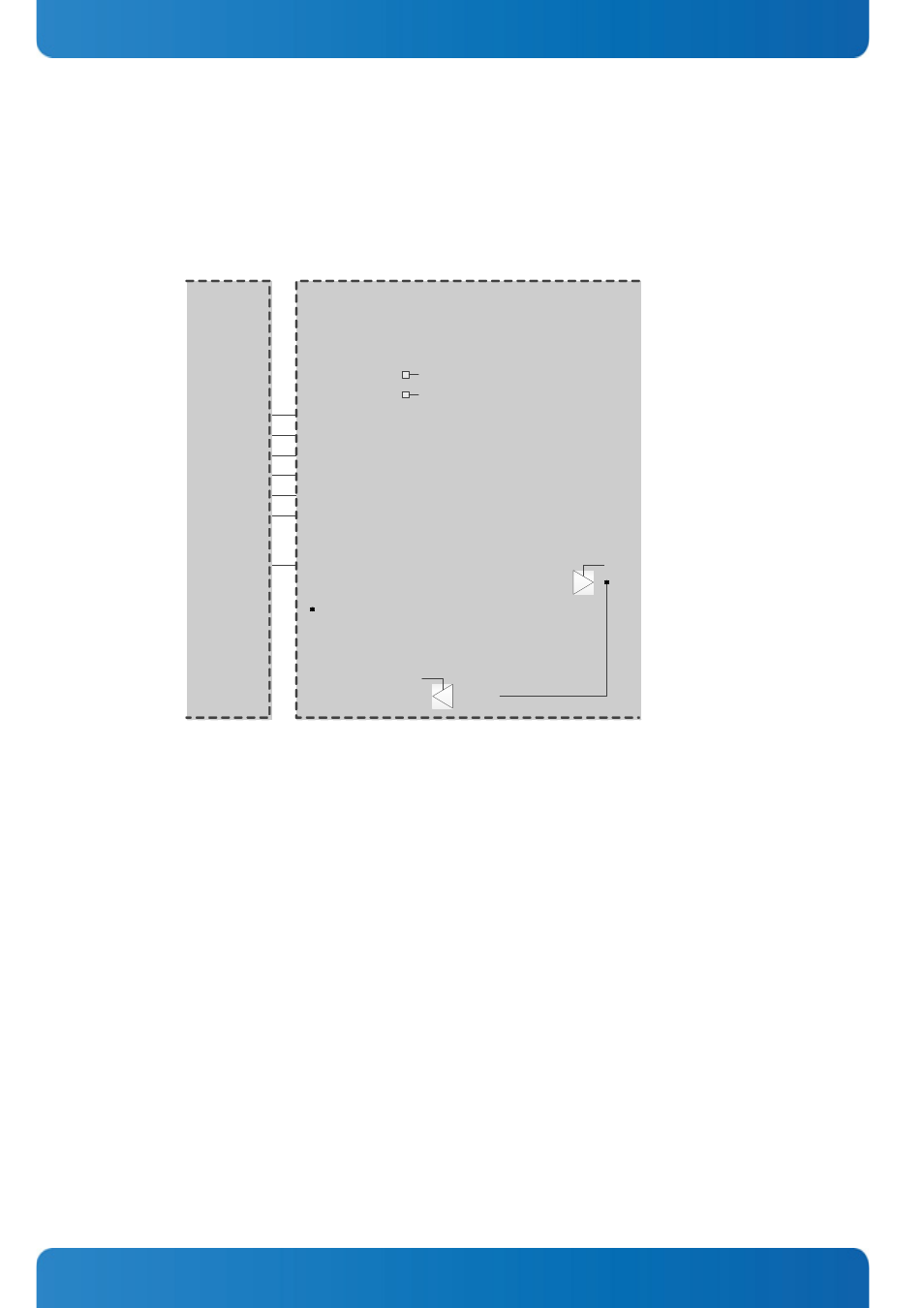
IRQs
The COMe-cP2020 provides five IRQ inputs which can be configured for edge/level, high and low active usage. The opera-
tional mode of the IRQs is programmed via the Carrier Interrupt Mode1 and Carrier Interrupt Mode2 registers. Refer to
Chapter 3 for further information.
The following figure demonstrates the IRQ routing of the COMe-cP2020.
Figure 2-1:
IRQ Routing Scheme
2.5.2.12
Miscellaneous (MISC)
These signals are normally pre-defined for an X86 architecture board and have no defined functionality on Power Architec-
ture CPUs. On the COMe-cP2020 these signals may be used as gerneral purpose output.
2.5.3
JTAG/Debug Interface
The COMe-cP2020 provides one JTAG/Debug connector, J4, to facilitate software debugging using an emulation probe. The
connector type is: 1x20_SAMTECH_ZF.
Watchdog
Timer
IRQ1..5#
CPU_IRQ7..11#
Carrier
Interrupt
Mode
0x374
0x375
Interrupt
Enable
Board
Interrupt
Pending
0x376
0x377
0x378
0x379
0x37A
0x37B
0x37C
0x37D
Interrupt
Multiplexer
0x380
0x381
1
5
1
PWROK
BATLOW#
WAKE0#
WAKE1#
CARRIER
COMe_cP2020
THERM#
SMB_ALERT#
0x28C
DIR
0x370
DIR
0x370
LM73_TEMP_ALERT#
RTC_INT#