Table 3-10, Table 3-11, Table 3-12 – Kontron COMe-cP2020 User Manual
Page 47
www.kontron.com
COMe-P2020 User Guide
47
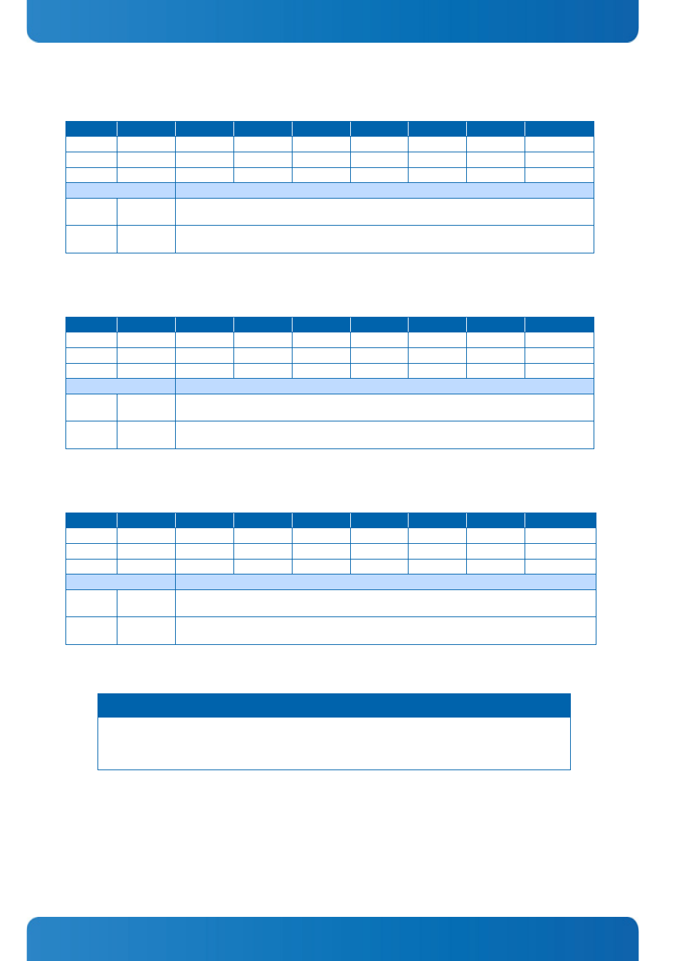
Table 3-10:
0x006: User eTSEC2 SGMII Mode Configuration Register
ACTION
D7
D6
D5
D4
D3
D2
D1
D0
READ
NU
NU
NU
NU
NU
NU
NU
cfg_sgmii2
WRITE
NU
NU
NU
NU
NU
NU
NU
cfg_sgmii2
POWER UP
1
1
1
1
1
1
1
1
BITFIELD
DESCRIPTION
[D0]
0
eTSEC2 Ethernet interface operates in SGMII mode and uses SGMII SerDes
lane 2 pins.
1
eTSEC2 Ethernet interface operates in standard parallel interface mode and
uses the TSEC2_* pins.
Table 3-11:
0x007: User eTSEC3 SGMII Mode Configuration Register
ACTION
D7
D6
D5
D4
D3
D2
D1
D0
READ
NU
NU
NU
NU
NU
NU
NU
cfg_sgmii3
WRITE
NU
NU
NU
NU
NU
NU
NU
cfg_sgmii3
POWER UP
1
1
1
1
1
1
1
1
BITFIELD
DESCRIPTION
[D0]
0
eTSEC3 Ethernet interface operates in SGMII mode and uses SGMII SerDes
lane 3 pins.
1
eTSEC3 Ethernet interface operates in standard parallel interface mode and
uses the TSEC3_* pins.
Table 3-12:
0x008: User eTSEC1 Width Configuration Register
ACTION
D7
D6
D5
D4
D3
D2
D1
D0
READ
NU
NU
NU
NU
NU
NU
NU
cfg_tsec_reduce
WRITE
NU
NU
NU
NU
NU
NU
NU
cfg_tsec_reduce
POWER UP
1
1
1
1
1
1
1
1
BITFIELD
DESCRIPTION
[D0]
0
eTSEC1 and eTSEC2 Ethernet interfaces operate in reduced pin mode
(either RTBI, RGMII, or RMII mode).
1
eTSEC1 and eTSEC2 Ethernet interfaces operate in their standard width TBI,
GMII, or MII mode.
N O T I C E
Register value is no more used to force CPU strapping, but register is used for checksum calculation!
(write Register value to 0x00). Equivalent CPU strapping is hard coded in CPLD depends on board vari-
ant, value is 0b.