Receiver alignment – Elecraft KX1 Manual User Manual
Page 46
E
LECRAFT
45
Receiver Alignment
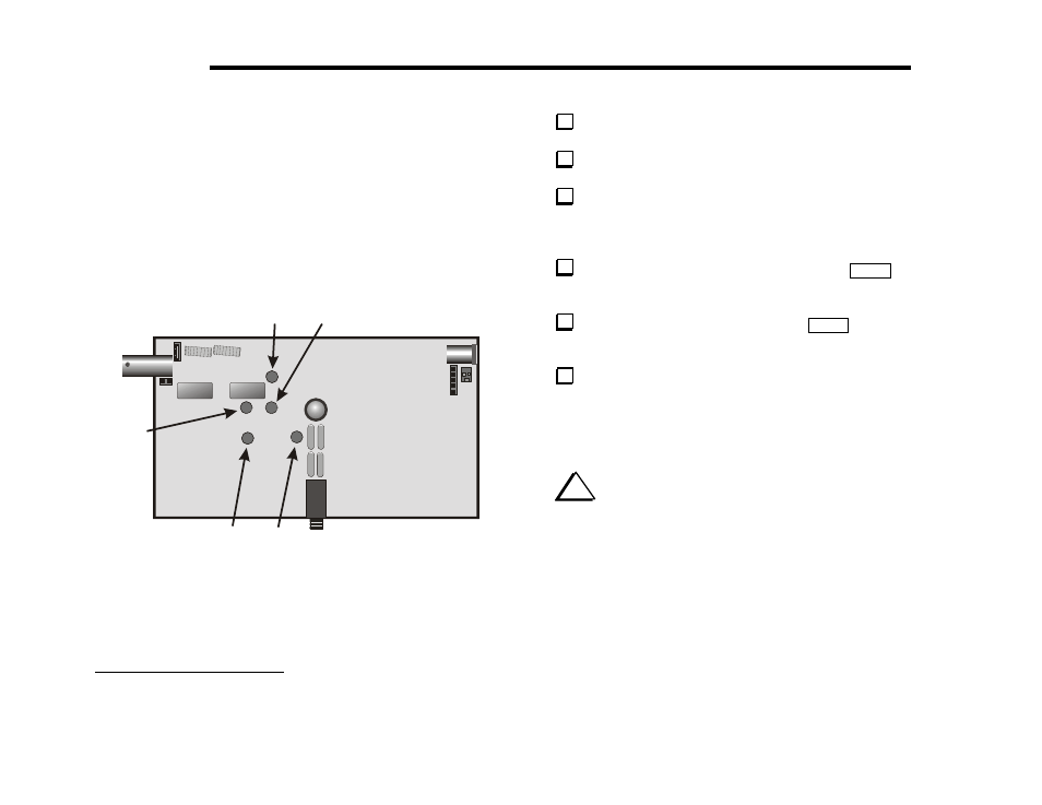
There are two receive band-pass filters to align. The trimmer
capacitors are adjusted through the bottom of the board as shown in
Figure 17. The 14 MHz (20 meter) filter has two adjustments, labeled
20A and 20B on the PC board, while the 7 MHz (40 meter) filter has
just one, labeled 40.
4
Two additional holes, labeled 30A and 30B, are provided for use with
the optional 30-meter or 30/80 meter modules (KXB30 or KXB8030).
The 14 MHz (20 m) trimmers must be aligned first, then the 7 MHz
(40 m) trimmer, as explained in the following steps.
K2
K1
20A
30B
30A
40
20B
BOTTOM OF BOARD
Figure 17. Trimmer Adjustments.
4
Only one adjustment is required on 40 meters because the first tuned circuit
is somewhat broadly resonant on this band, allowing the use of a fixed
capacitor.
Set the RF GAIN control fully clockwise.
Set the FILTER control fully clockwise.
Plug in a pair of headphones or an external speaker, and adjust
the AF GAIN control until you hear some background noise. If you do
not hear any noise, refer to Troubleshooting.
If the present band is not 14 MHz (20 m), tap
B AN D
twice
quickly to select it.
Set the VFO to about 14100 kHz. Tap
B AN D
if necessary to
verify that you're in the right 100-kHz segment.
Connect an appropriate antenna for the 20-meter band. At
minimum, connect approximately 15-30 feet (5 to 9 meters) of any
type of wire to the center conductor BNC connector J2. In general, the
longer and higher the antenna, the more signal strength that will be
available during receiver alignment.
i
Receiver alignment will be easiest if you use a controlled
signal, i.e. from a ham-band transmitter, signal generator or noise
generator. In all cases, use a signal that is weak enough to not activate
the KX1’s AGC; otherwise, it will be much more difficult to find the
correct settings for the trimmer capacitors. If you use a transmitter, be
sure to connect it to a dummy load and operate it at low power.