Elecraft KX1 Manual User Manual
Page 35
34
E
LECRAFT
Turn the board over so jack J1 is in the upper right corner and
locate the printed outline for C15 just to the left of electrolytic
capacitor C7 at the center of the board.
Directly above the location for C15 is one of the soldered encoder
pins. If it hasn’t been trimmed already, trim it flush.
Install the following capacitors so that about 1/16” (1 mm) of lead
shows between the capacitor and the board, so they can be folded
down against the board like you did with C39 earlier. DO NOT fold
these capacitors down against the board until you are instructed to
do so in later steps. If you fold them now, you will cover solder
pads you must reach to install other parts.
_ C15, .01 µF (103)
_ C3, .01 µF (103)
_ C14, 330 pF (331)
_ C9, 01 µF (103)
Install relay K1 (AGN2104H) to the left of R28 in the upper left
quadrant of the board as follows:
_ Position the relay on the board. It will only fit one way.
_ Hold the relay in place and solder just one of its middle pins
to hold it in place.
_ Re-heat the soldered pin while pressing down on the relay.
This will ensure that it is flush against the PC board.
_ Solder the remaining pins.
_ Trim all of the pins as short as possible.
Install relay K2 (AGN2104H) to the left of K1 following the same
procedure.
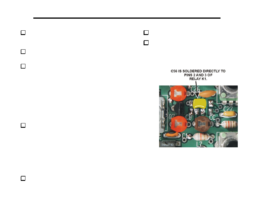
Turn the board face up so that KX1 is in the upper left corner.
Locate the pins for K1 in the upper right quadrant. Install C56
(68) between pins 2 and 3 of K1 as shown in Figure 13. There are no
solder pads for C56. Cut the two relay pins and solder the capacitor
leads directly to the pads for the relay pins. Be sure the capacitor does
not exceed 5/16” (7.9 mm) in height above the board.
Note: There are a number of components
shown in this picture that you have not
installed yet.
Figure 13. Installing Capacitor C56.