Kxat100 antenna tuning unit (atu) – Elecraft KXPA100 Manual User Manual
Page 41
41
KXAT100 Antenna Tuning Unit (ATU)
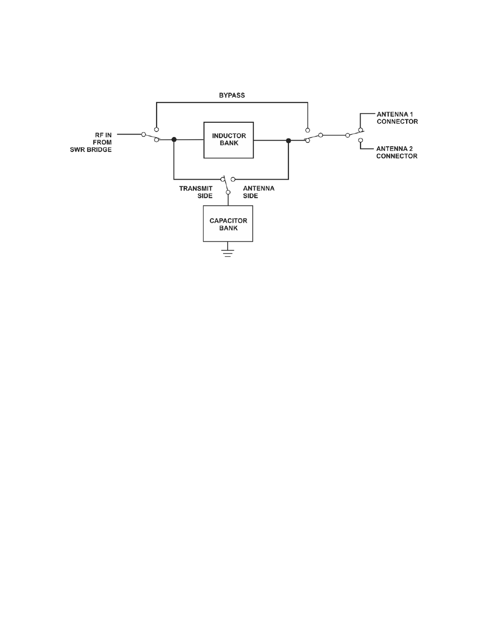
Figure 11 is a simplified block diagram of the ATU.
Figure 11. KXAT100 Antenna Tuning Unit Simplified Block Diagram.
The function of the ATU is to convert the impedance seen at the antenna connector to a 50 ohm non-reactive
load for the amplifier or driving transceiver as measured by the standing wave ratio (SWR) bridge at the
amplifier TR switch output.
The same control logic that controls the amplifier controls all of the ATU functions.
The ATU uses an “L” matching network with series inductance and shunt capacitance. Combinations of eight
capacitors and eight inductors are switched in by relays to provide up to 2624 pF of capacitance or up to 17370
nH of inductance. An algorithm switches through the inductors and capacitors and chooses whether the
capacitors are placed on the transmit or antenna side of the inductors to arrive at a tuning solution for the current
operating frequency.
The Amplifier circuit is kept in receive (RF routed through the TR switch but not the PA module) to protect the
relays while they are switching.
ATU Memories
To facilitate very rapid frequency changes, tuning solutions are stored in memory and recalled when returning to
that frequency. They will be recalled almost instantly when returning to that frequency later.
The entire spectrum from 1.8 through 60 MHz is divided into frequency segments and tuning information is
stored for each segment in which you have successfully completed a tune operation.
When starting a tune operation for a frequency segment that has no previously stored tuning solution, the ATU
logic first tries the settings in the nearest frequency segment that has tuning data.