Theory of operation – Elecraft KXPA100 Manual User Manual
Page 40
40
Theory of Operation
KXPA100 Amplifier
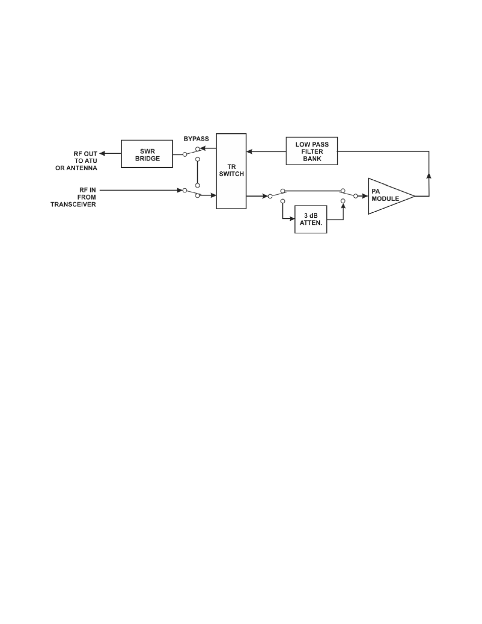
Figure 1 is a simplified block diagram of the amplifier.
Figure 10. KXPA100 Amplifier Simplified Block Diagram.
The Transmit-Receive (TR) switch routes the RF input and outputs as needed:
In receive mode (or when the amplifier is turned off) the RF input is routed to the RF output, passing
only through the SWR Bridge. When the amplifier is used with a KX3 connected via the KX3 to
KXPA100 Adapter Cable, the RF input is routed directly to the RF output at low power settings when
the amplifier is not needed.
In transmit the RF input is routed to the Power Amplifier (PA) module, and the RF from the Low Pass
Filter bank is routed to the SWR Bridge.
The Power Amplifier module amplifies the RF with two RD100HHF1 power MOSFETs.
The Low Pass Filter Bank contains low pass filters to suppress harmonic energy.
Control logic uses a firmware programmed MCU to control and monitor the amplifier operation:
When a key line low is sensed, the amplifier is switched into transmit mode provided no fault conditions
are present, the input signal is not in the 26 to 28 MHz range and an ATU tune operation is not
underway.
When RF is present at the input, the frequency of the signal is measured and the correct low pass filter is
switched into the signal path.
When the amplifier is connected to an Elecraft KX3 through the KX3 to KXPA100 Adapter Cable, the
logic receives band data from the KX3 and switches in the correct low pass filter. This provides a small
speed advantage in rapid band changes since it is not necessary to detect the frequency of the RF drive
before switching in the proper filter. However, the RF frequency sensing takes priority if it does not
agree with the band data to avoid transmitting with the incorrect filter selected.
The 3 dB attenuator is automatically switched in when the RF drive power exceeds 8 watts.
When a fault condition is detected the TR switch is inhibited so no RF power reaches the PA module
unless the applied RF drive is so high it may damage the TR switch. In that case the amplifier is
switched into bypass so no RF flows through the TR switch.