Corner identification and assembly, Includes offset and center-set glazing) – EFCO 433 Series User Manual
Page 59
June 2012
PART NO. Y017
Page 59 of 90
Series 433 Triple Set Installation Instructions
SECTION VII: Corners
(Includes Offset and Center-Set Glazing)
Corner Identification and Assembly
Proper identification of the required corner members is necessary to ensure a timely
installation process. See details of each corner variation on pages 55 through 57 in
Figures 23 through 33.
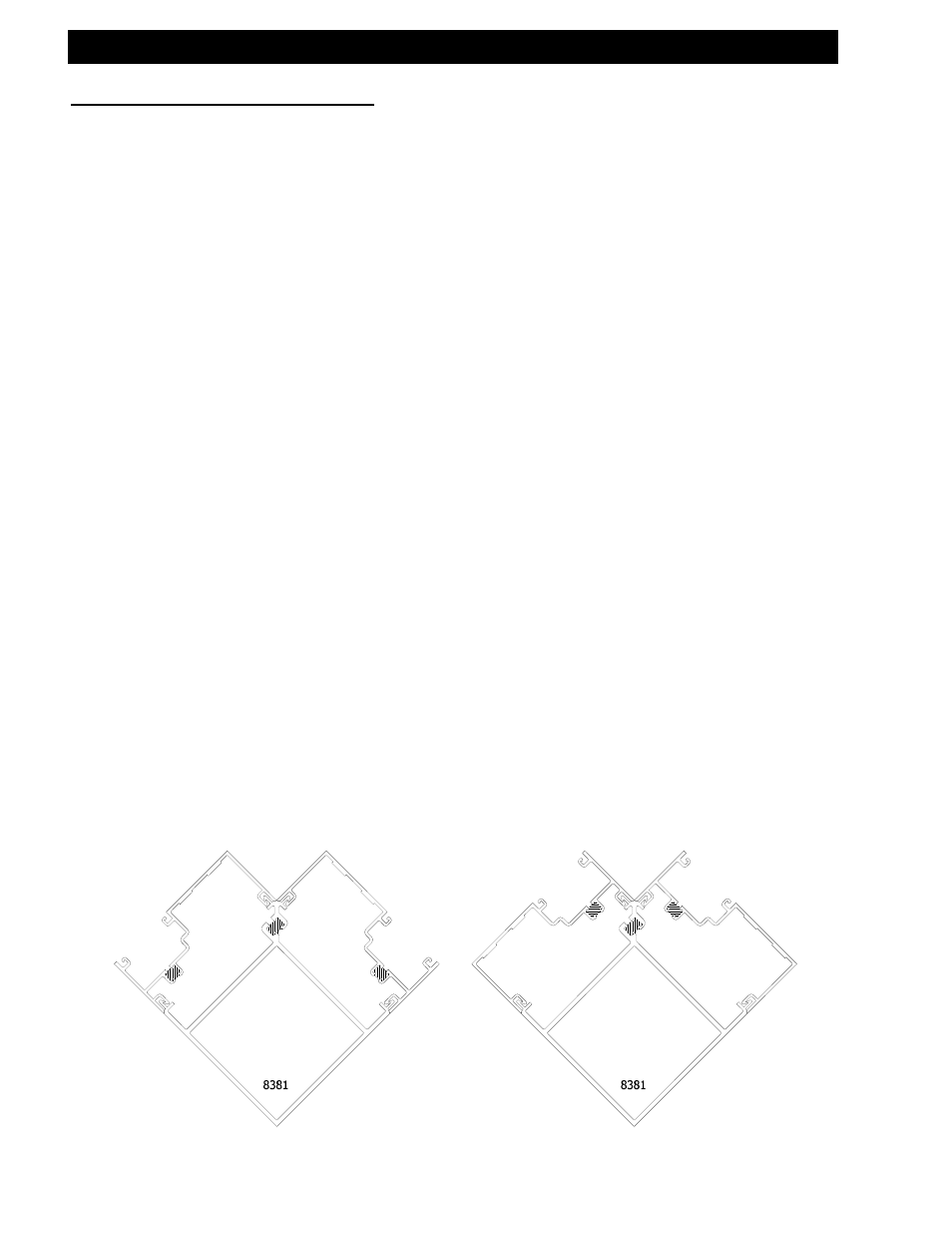
23) 90° outside set corner 27) 135° outside set corner
24) 90° inside set corner 28) 135° inside set corner
25) 90° center-set corner 29) 135° center-set corner
26) 90° multiple glass plane corner 30) 135° multiple glass plane corner
31) 90° outside set SSG corner
Both inside and outside corners can be accommodated with these details.
Figures 32 and 33 on page 61 show typical inside corners.
Determine that the subsill has been installed according to the instructions listed on
pages 46-51. Ensure the adjacent ladders are built with the appropriate mullion half to
be used with the corner mullion. Install the corner member into the subsill. It may be
necessary to temporarily brace the vertical corner member until the adjacent ladders
are installed and anchored. Install and snap one corner ladder completely, and then
install and snap the other onto the corner mullion.
If door openings are required on a run that incorporates a corner member, begin at the
doorframe and assemble towards the corner area with the required ladders.
Unassembled corner extrusions must be attached to the ladders, and the corner
member must be assembled after installation of both adjacent ladders.
[FIG. 23]
[FIG. 24]