Step 11) subsill splicing, Includes offset and center-set glazing), Fig. 21 – EFCO 433 Series User Manual
Page 57
June 2012
PART NO. Y017
Page 57 of 90
Series 433 Triple Set Installation Instructions
SECTION VI: Subsill Fabrication and Installation
(Includes Offset and Center-Set Glazing)
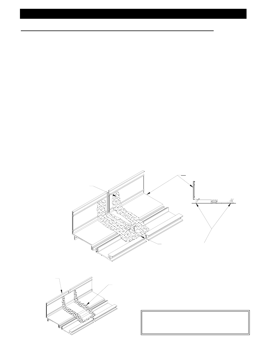
Step 11) Subsill Splicing
Verify that the subsill has been installed according to the instructions on pages 45
through 52. Splice areas are to be centered at a vertical mullion only. Maximum subsill
length between splices is 20’ to 25’. If a splice is required, leave a 1/4" gap between
the subsill ends at the splice area. Install and anchor the next run of subsill. Use a
silicone type sealant and a strip of WM01, bond breaker tape 1 7/8", wide and
approximately 7 1/2" long to create the splice material. Apply silicone to both sides of
the subsill ends and fill the void between the subsills as shown in Figure 21. Ensure
that the bond breaker tape is centered over the 1/4" gap, and set the bond breaker
tape into the sealant. Tool the silicone over the bond breaker tape to create a
watertight seal. If more sealant is required to cover the bond breaker tape, apply the
required amount. Ensure that the splice joint does not interfere with the anchor legs of
the sill and subsill. Making sure that the splice joint is located at the center of the
vertical mullions does this. Refer to the shop drawings or architectural drawings for
mullion centerlines.
AFTER INSTALLING THE BOND
BREAKER TAPE, TOOL THE
SEALANT OVER THE EDGE OF
THE TAPE TO PRODUCE A
WATERTIGHT SEAL.
FILL VOID BETWEEN
SUBSILLS WITH A SILICONE
TYPE SEALANT FROM THE
INTERIOR LEG TO THE BACK
OF THE EXTERIOR LEG.
AFTER THE SPLICE IS INSTALLED, APPLY A
COSMETIC SEAL TO THE INTERIOR GAP,
VERTICALLY UP THE SUBSILL SPLICE.
APPLY SILICONE TYPE SEALANT TO
CREATE A THIN BED TO SET THE
BOND BREAKER TAPE INTO.
[FIG. 21]
SUBSILL
2S44
SUBSILL
2S44
2S44 Shown
4471 Similar