Detex DTX-4300 User Manual
Page 47
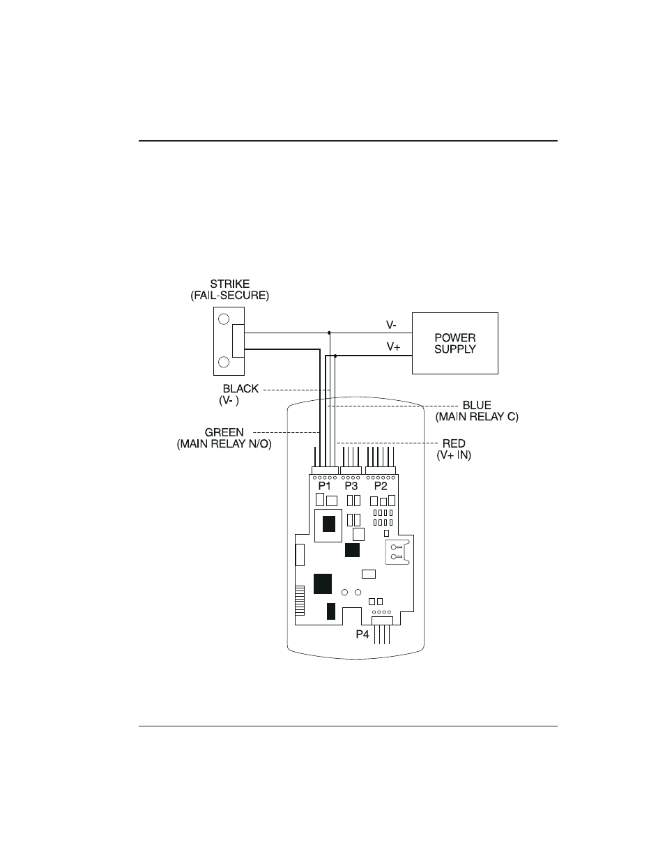
3.1.6 Wiring the Main
Relay
The door lock is wired to connector P1 on the prox.pad
plus main circuit board. Wiring for this 5-pin connector
is described in Table 2-2, Figure 3-6 provides an Electric
Strike (Fail Secure) wiring diagram, Figure 3-7 a
MagLock (Fail Safe) wiring diagram. Refer to the
power supply recommendations in Table 1-1 if neces-
sary.
P5
Figure 3-6 Electric Strike (Fail Secure) Wiring
Diagram
3.1 Wiring the prox.pad plus Unit
Chapter 3: Wiring
prox.pad plus Install/Program. Manual, PPP, D4b
3-11
Part No. 6105679, Rev. 1.1
See also other documents in the category Detex Safety:
- 02D Trim (3 pages)
- 08D Trim (5 pages)
- 01W Trim (2 pages)
- 02W Trim (4 pages)
- C Trim (6 pages)
- 08DM Trim (2 pages)
- 02DM Trim (2 pages)
- 01WM Trim (2 pages)
- 01CM Trim (2 pages)
- 08DN Trim (5 pages)
- 03R Trim for 60 Series (3 pages)
- 02WP Trim (2 pages)
- WSV Trim (4 pages)
- Exit Alarm (7 pages)
- Electric Signal Switching (1 page)
- Electric Integration (1 page)
- Delayed Egress With Magnetic Lock (7 pages)
- Delayed Egress With Magnetic Lock (16 pages)
- V40 Series Alarmed Rim Exit Devices (16 pages)
- 01P Trim (2 pages)
- 02A Trim (4 pages)
- BN Trim (2 pages)
- V40 ED (13 pages)
- V40 EE (16 pages)
- V50 EE (23 pages)
- V40 EX (1 page)
- AO19-1 Push (10 pages)
- AO19-1 Pull (9 pages)
- AO19-2 Push (11 pages)
- AO19-2 Pull (10 pages)
- AO19-3 (12 pages)
- Keyed Removable Mullions (4 pages)
- ECL-600 (4 pages)
- EAX-3500FK (1 page)
- EAX-4200 (2 pages)
- DTX-2100 (8 pages)
- DTX-2300 (32 pages)
- AT-5200 (2 pages)
- BE-961-1 (3 pages)
- VRA-143-B (10 pages)
- DDH-2250 (3 pages)
- CS-400 Momentary Models (2 pages)
- CS-400 Maintain Models (2 pages)
- DS-1481 (4 pages)