Installing system board options – Dell PowerEdge 2550 User Manual
Page 64
Back to Contents Page
Installing System Board Options
Dell™ PowerEdge™ 2550 Systems Installation and Troubleshooting Guide
Upgrading the Microprocessor or Installing a Secondary Microprocessor
Activating the Integrated RAID Controller
This section describes how to install expansion cards, memory, and microprocessors and how to activate the system's integrated redundant array of
independent disks (RAID) controller. Instructions for replacing the system battery are also included.
to locate the system board features.
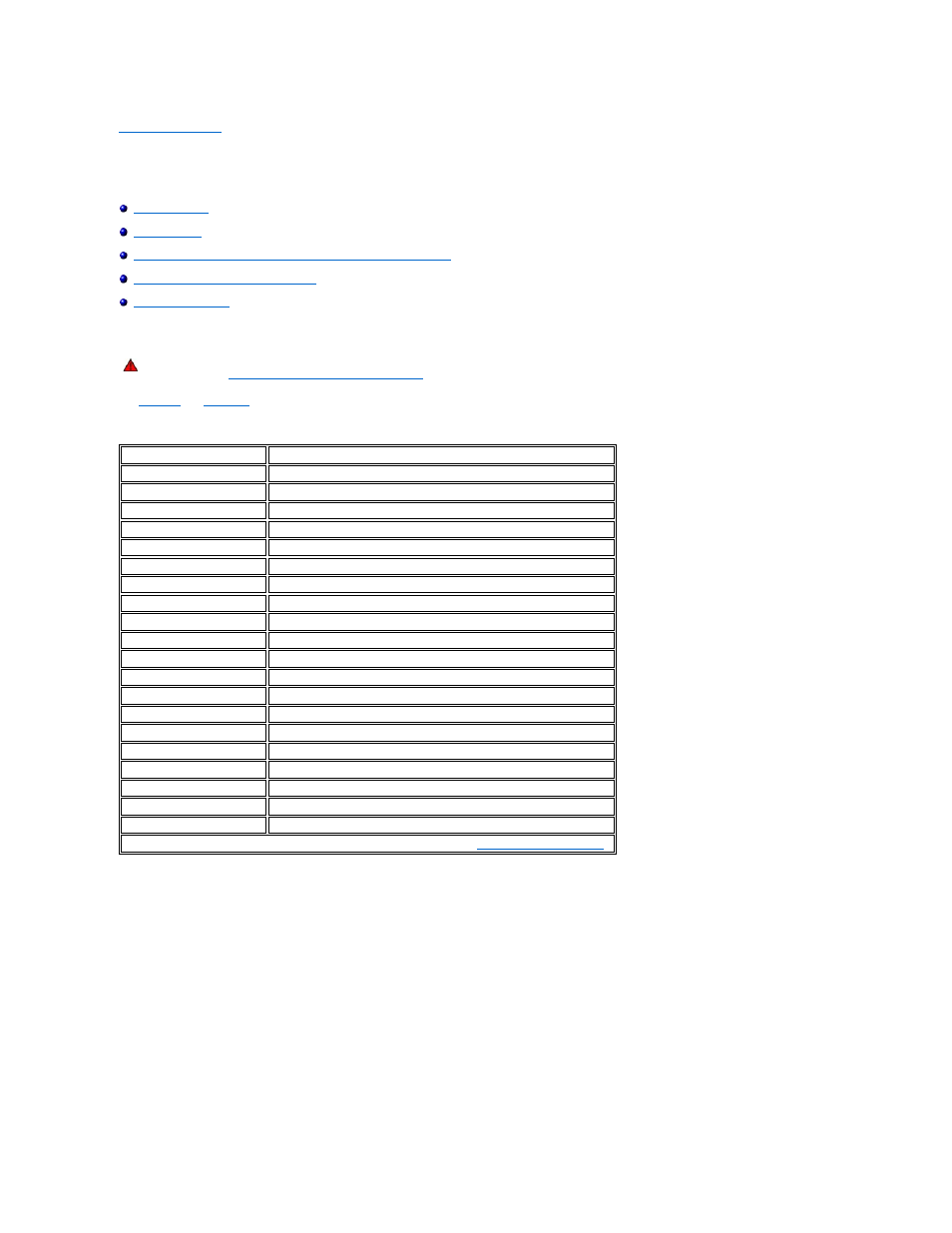
Table 8-1. System Board Connectors and Sockets
Figure 8-1. System Board Features
WARNING: Before you perform the procedures in this section, you must turn off the system and disconnect it from its electrical outlet. For more
information, see "
Safety First—For You and Your Computer
" in "Checking Inside the System."
Connector or Socket
Description
BACKPLANE
SCSI backplane board interface cable connector
BATTERY
Battery connector
COMn
Serial port connectors
DIMM_x
Memory module sockets
DIMM_RAID
Memory module socket for integrated RAID controller
INTRUS
Intrusion-alarm switch connector
KYBD
Keyboard connector
MOUSE
Mouse connector
NICn
NIC connector
PANEL
System control panel connector
PARALLEL
Parallel port connector
POWERn
Power connectors
PROC_n
Microprocessor connectors
RAID_KEY
Socket for integrated RAID controller hardware key
RAID_BATTERY
Connector for integrated RAID controller battery
RISER
PCI riser board connector
SCSIA, SCSIB
SCSI host adapter connectors
USBn
USB connectors
VGA
Video connector
VRMn
Primary and secondary VRM connectors
NOTE: For the full name of an abbreviation or acronym used in this table, see "
Abbreviations and Acronyms
."