System board connectors, Figure a, Table a – Dell PowerEdge 2550 User Manual
Page 16: For the designations, default settings, and
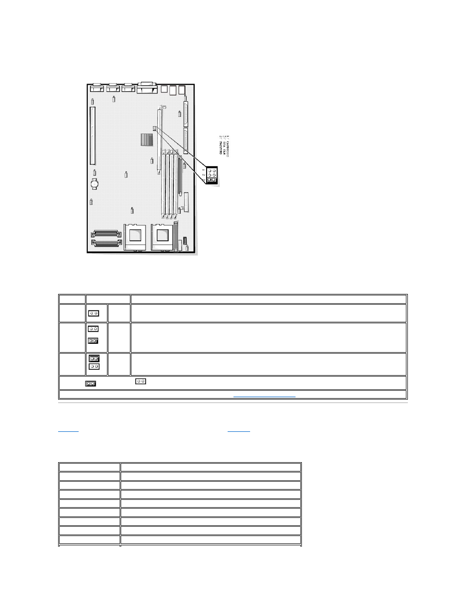
Figure A-3. System Board Jumpers
Table A-1. System-Board Jumper Settings
System Board Connectors
lists the connectors and sockets located on the system board. See
Figure 8
-1
for the location of these connectors and sockets.
Table A-2. System Board Connectors and Sockets
Jumper
Setting
Description
CARDBIOS
Reserved (do not change).
ISA_CLR
(default) The configuration settings are retained at system boot.
The configuration settings are cleared at next system boot. (If the configuration settings become corrupted to the point
where the system will not boot, install the jumper plug and boot the system. Remove the jumper before restoring the
configuration information.)
PASSWRD
(default) The password feature is enabled.
The password feature is disabled.
jumpered
unjumpered
NOTE: For the full name of an abbreviation or acronym used in this table, see "
Abbreviations and Acronyms
."
Connector or Socket
Description
BACKPLANE
Hot-pluggable SCSI backplane board interface cable connector
BATTERY
Battery connector
COMn
Serial port connectors; sometimes referred to as COM1 and COM2
DIMM_x
memory module sockets
DIMM_RAID
memory module socket for integrated RAID controller
INTRUS
Intrusion-alarm switch connectors
KYBD
Keyboard connector
MOUSE
Mouse connector