Dell PowerEdge 500SC User Manual
Page 30
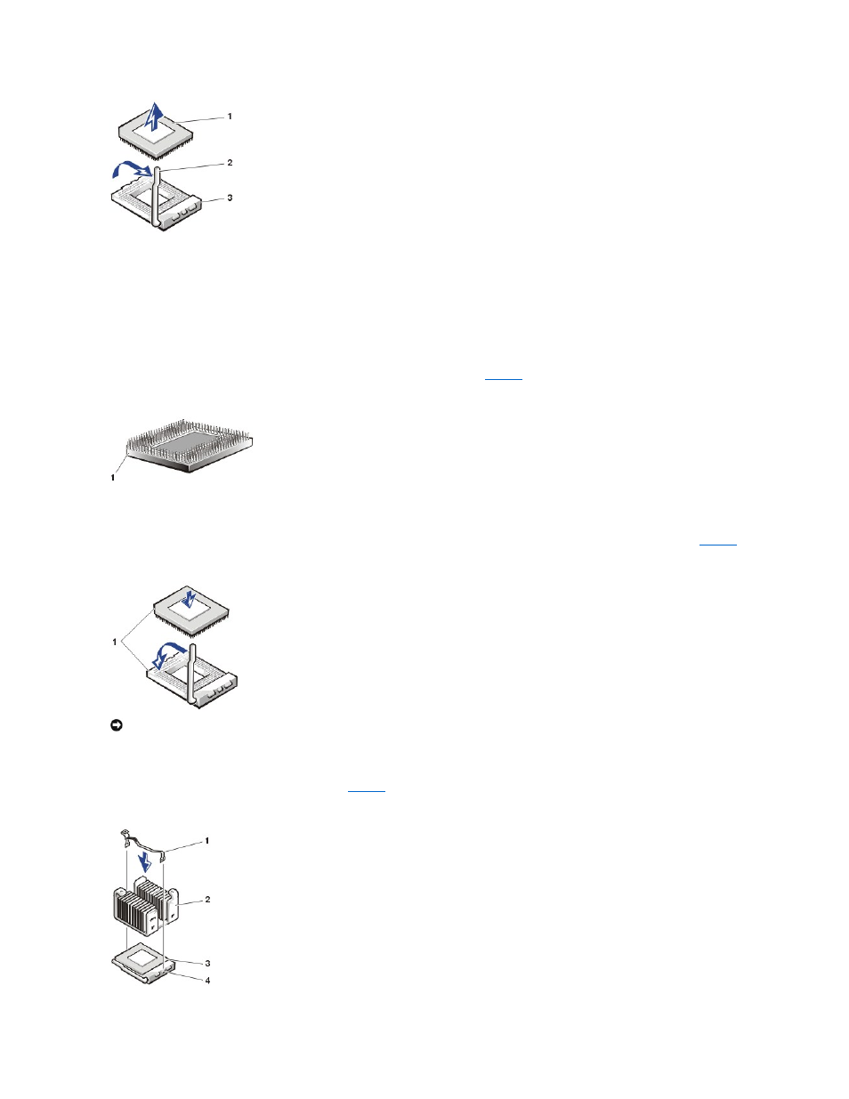
Replacing the Microprocessor and Heat-Sink Assembly
To install the additional or replacement microprocessor and heat sink assembly, perform the following steps.
This procedure assumes the system cover has been removed, the system power is off and power cords and peripheral cables are disconnected.
1.
Clean any thermal grease off the bottom of the heat sink with an alcohol wipe.
2.
If not already in the upright position, swing the ZIF arm up to the upright position.
The ZIF socket is now ready to accept a new microprocessor.
3.
Align the pin-1 corner of the microprocessor with the pin-1 corner of the ZIF socket (see
Figure 25. Pin 1 Identification
4.
Install the microprocessor in the ZIF socket.
Gently lower the replacement or upgrade microprocessor into the ZIF socket so that the processor pins exactly mate with the ZIF socket (see
).
Figure 26. Installing the Microprocessor
5.
When the microprocessor is fully seated in the ZIF socket, rotate the socket release lever down until it snaps into place, securing the microprocessor.
6.
Apply a measured amount of thermal grease to the top of the microprocessor.
7.
Place the heat sink on top of the microprocessor (see
Figure 27. Installing the Heat Sink and Securing Clip
1 Microprocessor
2 Release lever
3 ZIF socket
1 Pin 1 corner (golf triangle)
1 Pin 1 corner of microprocessor aligned with pin-1 corner of ZIF socket
NOTICE:
Do not force the processor module into the socket. Even slight pressure can bend the microprocessor module pins.
1 Securing clip
2 Heat-sink assembly
3 Microprocessor
4 ZIF socket