System cover and support beam, Removing the system cover and support beam – Dell PowerEdge 500SC User Manual
Page 17
The DC power cables from the power supply provide power to the system board, drives, and any expansion cards that connect to external peripheral.
The wide ribbon cables are the interface cables for internal drives. For the diskette drive, an interface cable connects the drive to an interface connector on the
system board or on an expansion card. For IDE devices, interface cables connect the devices to an IDE connector on the system board (for more information,
see "
During an installation or troubleshooting procedure, you may be required to change a jumper. For information on the system board jumpers, see "
System
Board Jumpers
."
System Cover and Support Beam
Removing the System Cover and Support Beam
1.
Lay the system on its right side, with the system foot stand off the edge of the work surface.
2.
Loosen the captive thumbscrew that secures the cover to the back of the system.
3.
Face the front of the system. Use your thumbs to press in both latches while pushing the cover backward. Move the cover back slightly, and then lift it
straight up (see
If necessary, use both hands and work one side at a time.
Figure 2. Removing the System Cover
4.
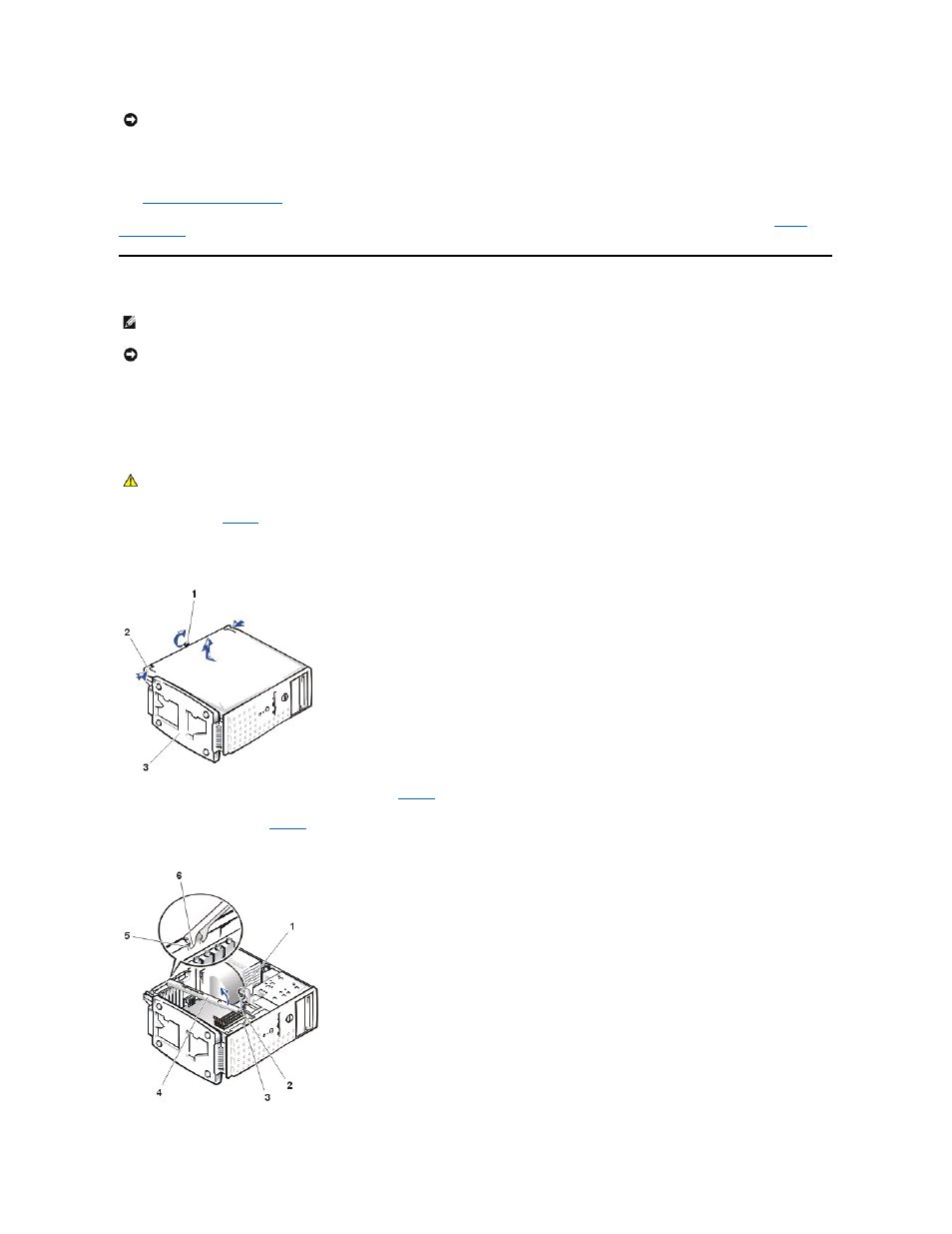
Remove the screw from the support beam as shown in
5.
Pull the front end of the support beam until it snaps free from its fastener. Rotate the front of the beam upward until the hinged tabs on the back of the
Figure 3. Removing the Support Beam
NOTICE:
Do not install a hard drive in the lower card-guide assembly bracket next to the card guides. Installing a drive in the lower card-guide
assembly bracket is not supported in this system.
NOTE:
Before you begin any of the procedures in this section, see "Safety Instructions" in your System Information document.
NOTICE:
To avoid damaging the system board, disconnect the power cable from the electrical outlet and from the back of the system, then press the
power button before you remove the system cover. The system board continues to receive a small amount of power when the system is turned off and
attached to an electrical outlet.
CAUTION:
To prevent cuts, keep your hands clear of the metal edges on the system as you slide back the cover.
1 Thumbscrew
2 Cover release latch
3 System foot stand
1 Screw
2 Lock tab
3 Slot
4 Support beam
5 Slots (2)
6 Hinged tabs (2)