Control panel assembly, Drives, Removing and replacing drives – Dell PowerEdge 500SC User Manual
Page 19
2.
Secure the drive cage to the system with the screw you removed in step 5 of "
3.
Connect the interface cable and the power cable to all drives installed in the drive cage.
4.
Replace the bezel.
5.
Replace the system cover.
Control Panel Assembly
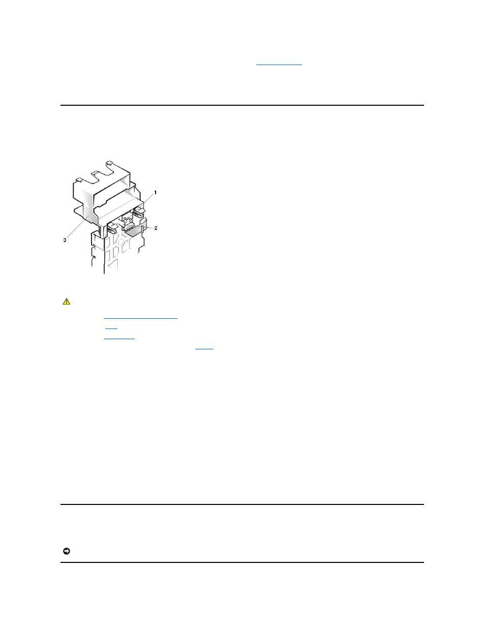
In Figure 6, the control panel is shown removed from the system chassis.
Figure 6. Control-Panel Removal
To remove the control panel assembly, perform the following steps.
1.
2.
Remove the
.
3.
.
4.
Remove the screws securing the drive bracket (see
5.
While pressing the four card guide assembly securing clips, slide the drive bracket back until the clips are no longer securing the assembly to the front
panel.
6.
Press the card guide assembly securing clip located in the diskette drive bay and slide the card guide assembly and hard drive toward the back of the
system and lift them out of the system.
7.
Disconnect the ribbon cable from the system board connector (FRONT PANEL).
8.
Press the control panel assembly securing clip that secures the control panel bracket to the card guide assembly, and lift the control panel up and out
of the card guide assembly.
To replace the control panel assembly, perform the following steps.
1.
Align the control panel assembly with the card guide assembly alignment pins and press down until the control panel assembly snaps into place.
2.
Connect the ribbon cable to the system board connector (FRONT PANEL).
3.
Align the card guide assembly's four securing clips with the slots in the front panel and press the assembly and hard drive toward the front of the
system until it snaps into place.
4.
Replace the diskette drive.
5.
Replace the screws securing the drive bracket
6.
Replace the bezel.
7.
Replace the system cover and support beam.
Removing and Replacing Drives
Your system includes bays or brackets for up to three 1-inch IDE hard drives or two 5.25-inch drives.
1 Control panel board
2 Securing clip
3 Card guide assembly
CAUTION:
Read the safety instructions in your System Information document.
NOTICE:
When replacing a hard drive, set the jumpers on the replacement hard drive to match the jumpers on the hard drive you removed. For
additional information about jumper settings on IDE drives, see "Configuring the EIDE Subsystem" in your system Installation and Troubleshooting Guide.