Removing and replacing parts, Overview, Inside the system – Dell PowerEdge 500SC User Manual
Page 16: Recommended tools
Back to Contents Page
Removing and Replacing Parts
Dell™ PowerEdge™ 500SC Systems Service Manual
Overview
The procedures in this guide require that you remove the cover and work inside the system. While working inside the system, do not attempt to service the
system except as explained in this manual and elsewhere in Dell documentation. Always follow the instructions closely. Make sure to review all of the
procedures in "Safety Instructions" in your System Information document.
This section provides servicing procedures for components inside the system. Before you start any of the procedures in this section, perform the following
tasks:
l
Perform the procedures described in "
External Visual Inspection
."
l
Read the safety information in the System Information document.
When there is no replacement procedure provided, use the removal procedure in reverse order to install the replacement part.
Recommended Tools
You need the following items to perform the procedures in this section:
l
The system diagnostics diskette set appropriate for your system
l
System User's Guide
l
System Installation and Troubleshooting Guide
l
Key to the system keylock
l
#1 and #2 Phillips screwdriver
l
Wrist grounding strap
Inside the System
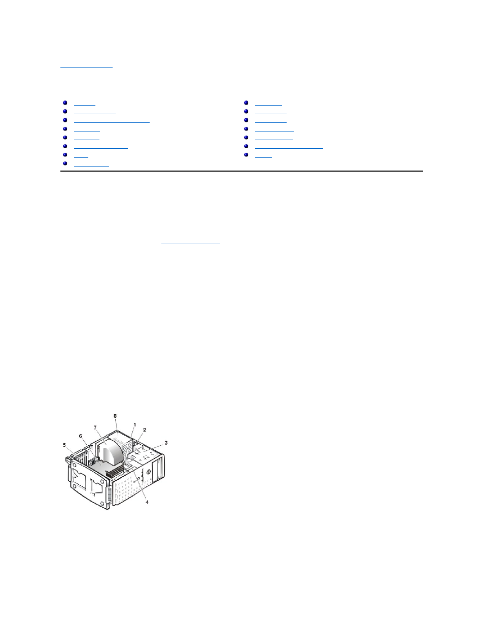
In Figure 1, the system cover is removed to provide an interior view. Refer to this illustration to locate interior features and components discussed later in this
manual.
Figure 1. Inside the System (Right-Side View)
The system board can accommodate up to five PCI expansion cards (two cards at 64-bit/66 MHz or 64-bit/33 MHz, and three cards at 32-bit/33 MHz).
The drive cage contains two externally accessible, 5.25-inch drive bays that provide space for up to two drives, including a CD or DVD drive and one other
device, such as a tape drive. The drive cage also provides space for up to two 1-inch IDE hard drives.
Additionally, the card guide assembly provides two additional brackets for a 3.5-inch diskette drive and a 1-inch IDE hard drive.
1 Drive cable
2 Power cables
3 Drive cage
4 Card guide assembly
5 Expansion card filler brackets (5)
6 System board
7 Cooling fan shroud
8 Power supply