Processor, Removing memory modules – Dell PowerEdge 700 User Manual
Page 63
8.
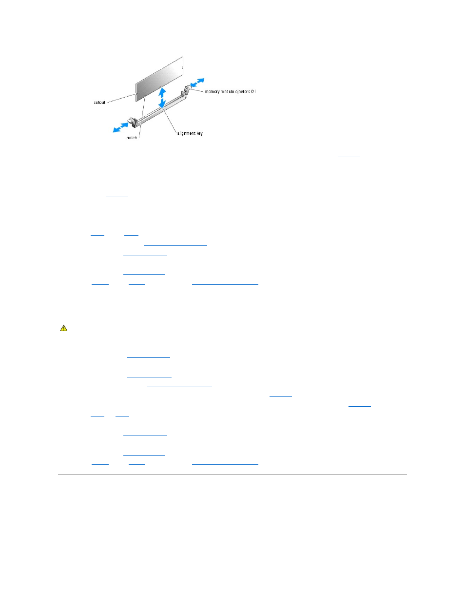
Align the memory module's edge connector with the alignment key, and insert the memory module in the connector. See
.
The memory module connector has an alignment key that allows the memory module to be installed in the connector in only one way.
9.
Press down on the memory module with your thumbs while pulling up on the ejectors with your index fingers to lock the memory module into the
connector. See
.
When the memory module is properly seated in the connector, the memory module ejectors should align with the ejectors on the other connectors with
memory modules installed.
10.
Repeat
of this procedure to install the remaining memory modules.
11.
Install the cooling shroud. See "
12.
Install the cover. See "
Replacing the Cover
" in "Troubleshooting Your System."
13.
Stand the system upright.
14.
Install the bezel. See "
Installing the Bezel
" in "Troubleshooting Your System."
15.
of the procedure in "
Removing Memory Modules
1.
Turn off the system, including any attached peripherals, and disconnect the system from the electrical outlet.
2.
Remove the bezel. See "
Removing the Bezel
" in "Troubleshooting Your System."
3.
Lay the system on its right side.
4.
Remove the cover. See "
Removing the Cover
" in "Troubleshooting Your System."
5.
Remove the cooling shroud. See "
6.
Locate the memory module connectors from which you will remove memory modules. See
Figure A
-3
.
7.
Press down and outward on the memory module connector ejectors until the memory module pops out of the connector. See
8.
Repeat
and
of this procedure to remove any other memory modules.
9.
Install the cooling shroud. See "
10.
Install the cover. See "
Replacing the Cover
" in "Troubleshooting Your System."
11.
Stand the system upright.
12.
Install the bezel. See "
Installing the Bezel
" in "Troubleshooting Your System."
13.
of the procedure in "
Processor
To take advantage of future options in speed and functionality, you can upgrade the processor.
The processor and its associated cache memory are contained in a PGA package that is installed in a ZIF socket on the system board.
CAUTION:
See your System Information Guide for complete information about safety precautions working inside the computer and protecting
against electrostatic discharge.