Dell PowerEdge 700 User Manual
Page 61
Memory Module Installation Guidelines
The memory module sockets are arranged in banks (1 and 2) on two channels (A and B). Unless only one 256-MB memory module is installed, the modules
must be installed in identical pairs. For example, if you are installing 512-MB of total system memory, sockets DIMM1_A and DIMM1_B (bank 1) must contain
256-MB memory modules.
Starting with the connector closest to the processor, the memory module sockets are labeled "DIMM1_A" through "DIMM2_B" (see
Figure A
-3
). When installing
the memory modules, use the following guidelines:
l
Use only DDR-400 memory modules.
l
If you are installing one 256-MB memory module, install the module in the DIMM1_A socket.
l
If you are installing 512-MB or more of total memory, install identical memory modules in a bank.
The memory module banks are identified as follows:
¡
Bank 1: DIMM1_A and DIMM1_B
¡
Bank 2: DIMM2_A and DIMM2_B
l
Unless only one 256-MB memory module is installed, bank 1 must contain two identical memory modules. However, you can configure bank 1 and bank
2 with different size memory modules.
l
Installing three memory modules is not supported.
l
Install memory modules in bank 1 (DIMM1_x) before installing memory modules in bank 2 (DIMM2_x).
lists the supported memory module configurations for the system.
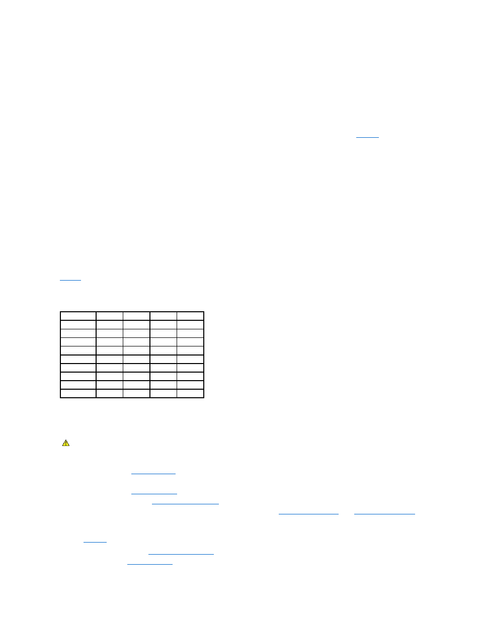
Table 6-1. Supported Memory Module Configurations
Performing a Memory Upgrade
1.
Turn off the system, including any attached peripherals, and disconnect the system from the electrical outlet.
2.
Remove the bezel. See "
Removing the Bezel
" in "Troubleshooting Your System."
3.
Lay the system on its right side.
4.
Remove the cover. See "
Removing the Cover
" in "Troubleshooting Your System."
5.
Remove the cooling shroud. See "
6.
Install or remove memory modules as necessary to reach the desired memory total. See "
."
See
Figure A
-3
to locate the memory module connectors.
7.
Install the cooling shroud. See "
8.
Install the cover. See "
Replacing the Cover
" in "Troubleshooting Your System."
Total Memory DIMM1_A DIMM2_A DIMM1_B DIMM2_B
256 MB
256 MB
None
None
None
512 MB
256 MB
None
256 MB
None
1 GB
256 MB
256 MB
256 MB
256 MB
1 GB
512 MB
None
512 MB
None
1.5 GB
512 MB
256 MB
512 MB
256 MB
2 GB
512 MB
512 MB
512 MB
512 MB
2 GB
1 GB
None
1 GB
None
3 GB
1 GB
512 MB
1 GB
512 MB
4 GB
1 GB
1 GB
1 GB
1 GB
CAUTION:
See your System Information Guide for complete information about safety precautions working inside the computer and protecting
against electrostatic discharge.