Side gauge wheel adjustment – Great Plains YP4425A Operator Manual User Manual
Page 77
Great Plains Manufacturing, Inc.
Adjustments
73
2012-02-23
401-805M
Side Gauge Wheel Adjustment
Refer to Figure 87 and Figure 88
Disc-to-wheel angle and clearance ideally has the wheel
just touching the disc when the wheel is raised to
planting depth (is up against the stop set by the “T”
handle. The goal is to have both discs and wheels turn
freely, but keep soil and trash from getting between them.
These two adjustments interact with each other.
Changing one requires at least checking the other.
In addition to changing the disc angle due to changing
depth or new field conditions, these two settings may
need attention over time as the disc and wheels wear
from normal use. This adjustment will also need to be
made if any opener components are replaced.
Refer to Figure 88
For 2in (5.1cm) planting depth, adjust side gauge wheel
angle so wheels contact row unit discs at the bottom of
wheel. Check with row units in soil so wheels are held
up.
At the same time, keep side gauge wheels close to
opener discs so openers do not plug with soil or trash.
Note: Wheels should be out far enough so discs and
wheels turn freely.
Refer to Figure 90 on page 74
To adjust side gauge wheels:
1.
Raise the planter and install lift cylinder locks.
2.
Loosen hex-head bolt
. Move wheel and arm out
on O-ring bushing.
3.
Loosen pivot bolt
Turn hex adjuster
so indicator
notch
is at 5 o’clock to 7 o’clock.
Note: Use this as the starting point for adjustment.
4.
Move wheel arm in so side gauge wheel contacts
row unit disc. Tighten hex-head bolt
to clamp arm
around bushing and shank.
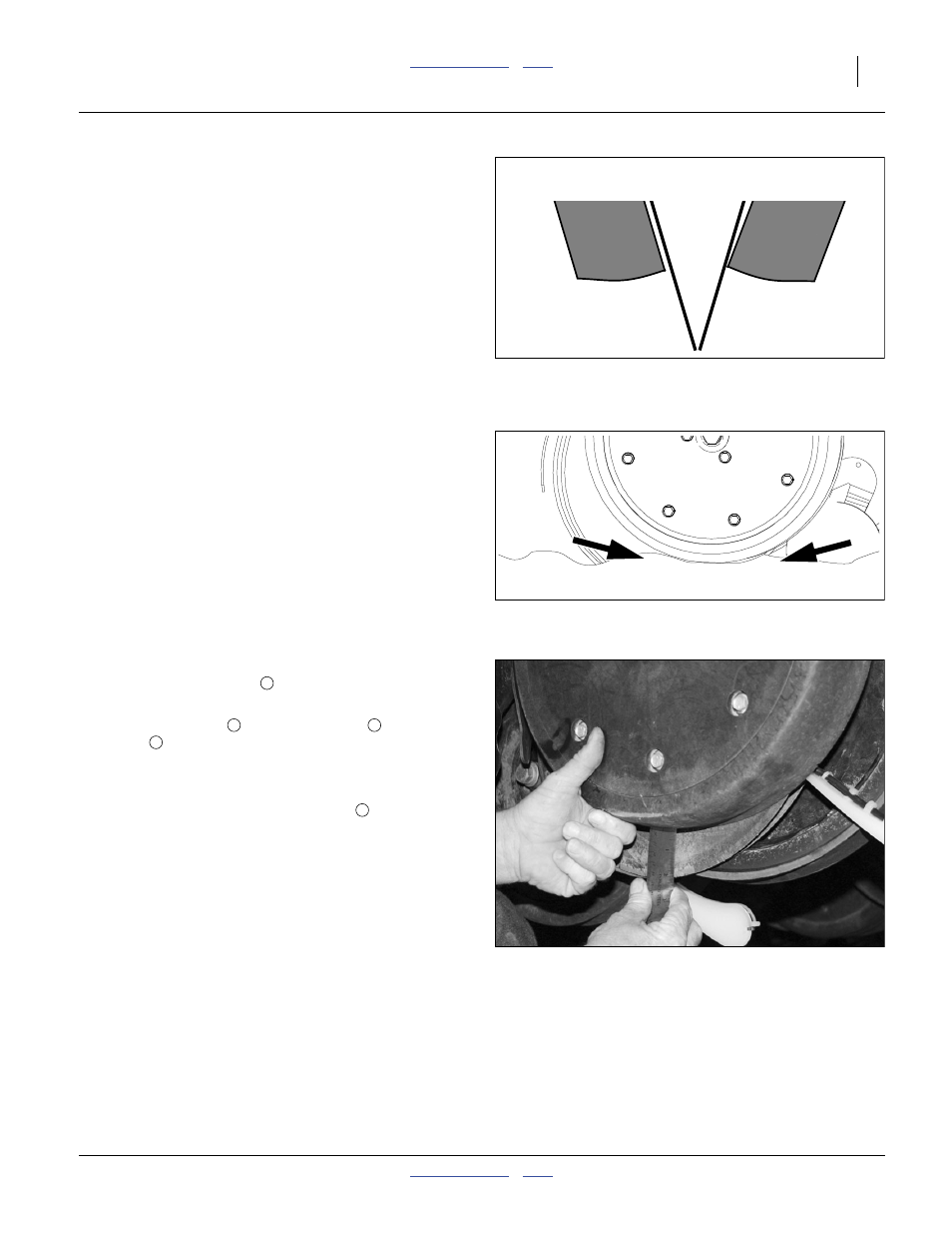
Check wheel-to-disc contact at 2 inch (5.2 cm)
planting depth. Lift wheel 2 inches (5 cm), check
contact and release. When let go, wheel should fall
freely.
• If wheel does not contact disc at bottom to area where
blade leaves contact with soil, move hex adjuster until
wheel is angled for proper contact with disc.
Figure 87
Disc/Gauge Wheel Alignment
Incorrect
Correct
Side Gauge
Wheel
Opener
Discs
Side Gauge
Wheel
Figure 88
Opener-Gauge Wheel Contact
22531
Contact Within this Area
Figure 89
Checking Wheel/Disc Contact
26129