Appendix b - initial and option setup, Pre-delivery items, Install upper marker components – Great Plains YP4425A Operator Manual User Manual
Page 152: Install press wheels
401-805M
2012-02-23
148
YP4425A
Great Plains Manufacturing, Inc.
Appendix B - Initial and Option Setup
Pre-Delivery Items
These items are normally completed by the Great Plains
dealer prior to releasing the implement to the customer.
Install Upper Marker Components
Marker discs and end tubes are removed for shipping.
Refer to Figure 136
The end tube
may be inserted into the outer marker
arm
in any of four orientations. Great Plains
recommends that the spindle adjustment allow the disc
to pivot back, away from the direction of travel
.
If the markers are extended for this work, also set the
initial marker extension based on the row spacing.
At each marker, select one each:
marker disc and tube assembly
806-110C U-BOLT 5/8-11 X 3 1/32 X 4 1/2
and two sets:
803-021C NUT HEX 5/8-11 PLT
804-022C WASHER LOCK SPRING 5/8 PLT
2.
Insert the end tube
into the outer marker arm
Insert to initial marker extension value, or about
halfway if extension is not known. Secure with
U-bolt
, lock washers
and nuts
.
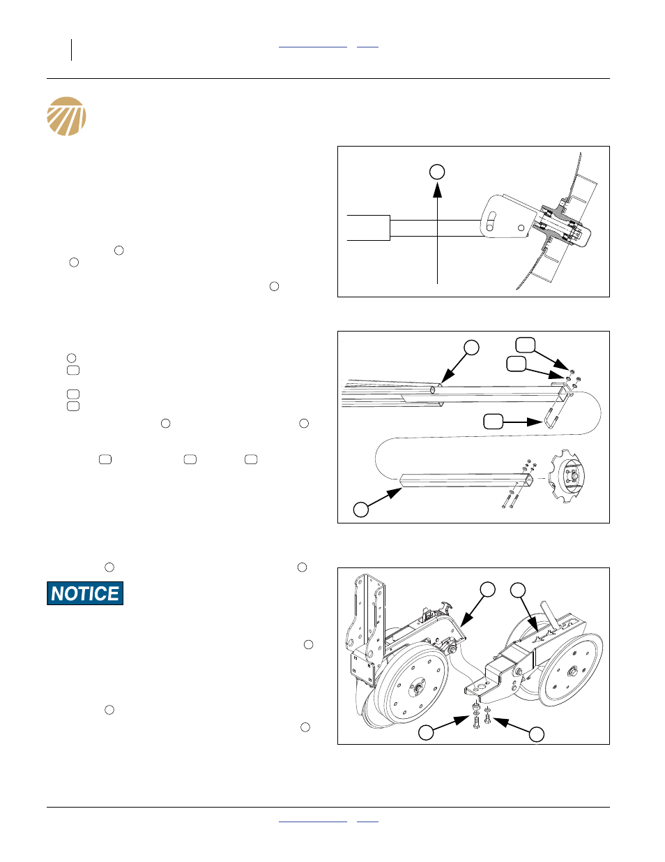
Install Press Wheels
To meet highway clearance requirements, press wheel
arms and wheels on wing rows are not factory-installed.
1.
Remove and save the
1
⁄
2
-13x1in. hex head bolt and
washer
at the back of an incomplete row unit
There are four bolts at this location. Remove only the hex head
bolts. Do not loosen or remove the square head bolts forward.
2.
Remove and save the
1
⁄
2
-13x1
1
⁄
2
in. hex head bolt
,
washer, and eccentric adjuster nut.
3.
Align the
1
⁄
2
in. holes in the press wheel assembly
with the
1
⁄
2
-13 tapped holes in the row unit, loosely
assemble with the
1
⁄
2
-13x1in. hex head bolt and
washer
.
4.
Loosely screw in the
1
⁄
2
-13x1
1
⁄
2
in. hex head bolt
washer, and eccentric adjuster nut. Rotate the
adjuster to visually align the press wheel assembly
with the row unit, and tight the adjust and both bolts.
Figure 136
Marker Disc Spindle Orientation
11757
T
T
36
1
35
34
2
Figure 137
Marker Final Assembly
29177
36
34
35
2
36
35
34
Figure 138
25AP Press Wheel Assembly
25383
1
2
4
3
3