Dual marker speed adjustment, Hitch shims – Great Plains 3PYP Operator Manual User Manual
Page 93
Great Plains Manufacturing, Inc.
Maintenance and Lubrication
89
2014-09-09
401-312M
Dual Marker Speed Adjustment
Crushing and Sharp Object Hazards:
You may be injured if hit by a folding or unfolding marker.
Markers may fall quickly and unexpectedly if the hydraulics
fail. Never allow anyone near the planter when folding or
unfolding the markers.
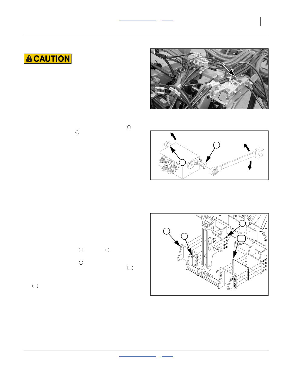
Refer to Figure 108 and Figure 109
Adjust folding speed for dual markers with hex
adjustment screws on the sequence valve body. The
valve sequence body is top left center section, near front.
Loosen jam nuts before making adjustments.
There is one adjustment screw for fold-out speed
and
one for fold-down speed
. You can identify adjustment
screws by markings stamped in valve body.
Turn adjustment screws clockwise (S: slower) to
decrease folding speed and counterclockwise (F: faster)
to increase folding speed.
With tractor idling at a normal operating speed, adjust
marker folding to a safe speed. Excessive folding speed
could damage markers and void the warranty.
After adjusting the folding speed, tighten jam nuts on hex
adjustment screws to hold settings.
Hitch Shims
Refer to Figure 110
(an exploded view - remove only specified parts)
If the planter tends to pull to the right or left, inserting,
moving or stacking hitch shims may correct the problem.
The standard planter has one shim installed on the left. A
spare hitch shim was shipped with the planter.
To remove or insert a shim:
1.
Loosen the eight nuts
and bolts
on the lower
hitch, only on the side to be changed.
2.
At the four set screws
, loosen the four jam nuts.
Drive the set screws in until the existing shim
is
free, or the gap is large enough to insert a shim.
3.
From the top, insert or remove:
401-943D SHIM HITCH FLANGE
4.
Back out the four set screws. Tighten the eight nuts
and bolts. Turn the set screws in until they make
contact. Secure them with the four jam nuts.
Figure 108
Marker Sequence Valve Location
25440
Figure 109
Marker Extension Adjustment
14048
F
S
S
2
1
Figure 110
Remove Right Hitch Shim
29859
1
15
2
3
1
2
3
15
15