Row unit lock-up – Great Plains 3PYP Operator Manual User Manual
Page 68
64
3PYP
Great Plains Manufacturing, Inc.
401-312M
2014-09-09
Row Unit Lock-Up
Alternate twin-row units (the rear units) can be pinned in
the up position to accommodate single-row spacing.
Refer to Figure 69
The lock-up pins
for each rear row unit are located in a
storage hole
in the row unit mount. To lock up a unit,
the unit must be raised, and the pin moved to the lock-up
hole
in the row unit shank.
Note: If you lose a pin, the replacement part number is
805-033C
1.
Raise the planter. Although this adjustment can be
made with the planter lowered, the springs will be in
tension, and will require more effort. The extra force
may also damage tools.
2.
Install lift assist cylinder locks. Lower parking stands.
3.
Unhitch tractor. Move row mode spacer on an older
planter (see page 158).
4.
Set the down pressure springs be set to the
minimum setting, per the instructions on page 61.
5.
Raise the row unit high enough that the hole for the
pin is above the lower parallel arm. This can be done
in several ways, including:
a. use a hoist at the rear of the shank
b. use a jack under the shank extension
Machine Damage Risk:
Raising a row unit on a block by lowering the planter is risky.
Full lowering can easily damage components, and hydraulic
failure is a safety hazard.
Crushing and Sharp Object Hazards:
Do not attempt to lift the row unit by hand. The weight of the
unit, plus the force of the springs (even at minimum) is too
great (plus, a free hand is needed for pin insertion). Even with
multiple people lifting, hand-lifting is unsafe - there are
numerous sharp edges, and the row unit will snap down
violently if a grip is lost.
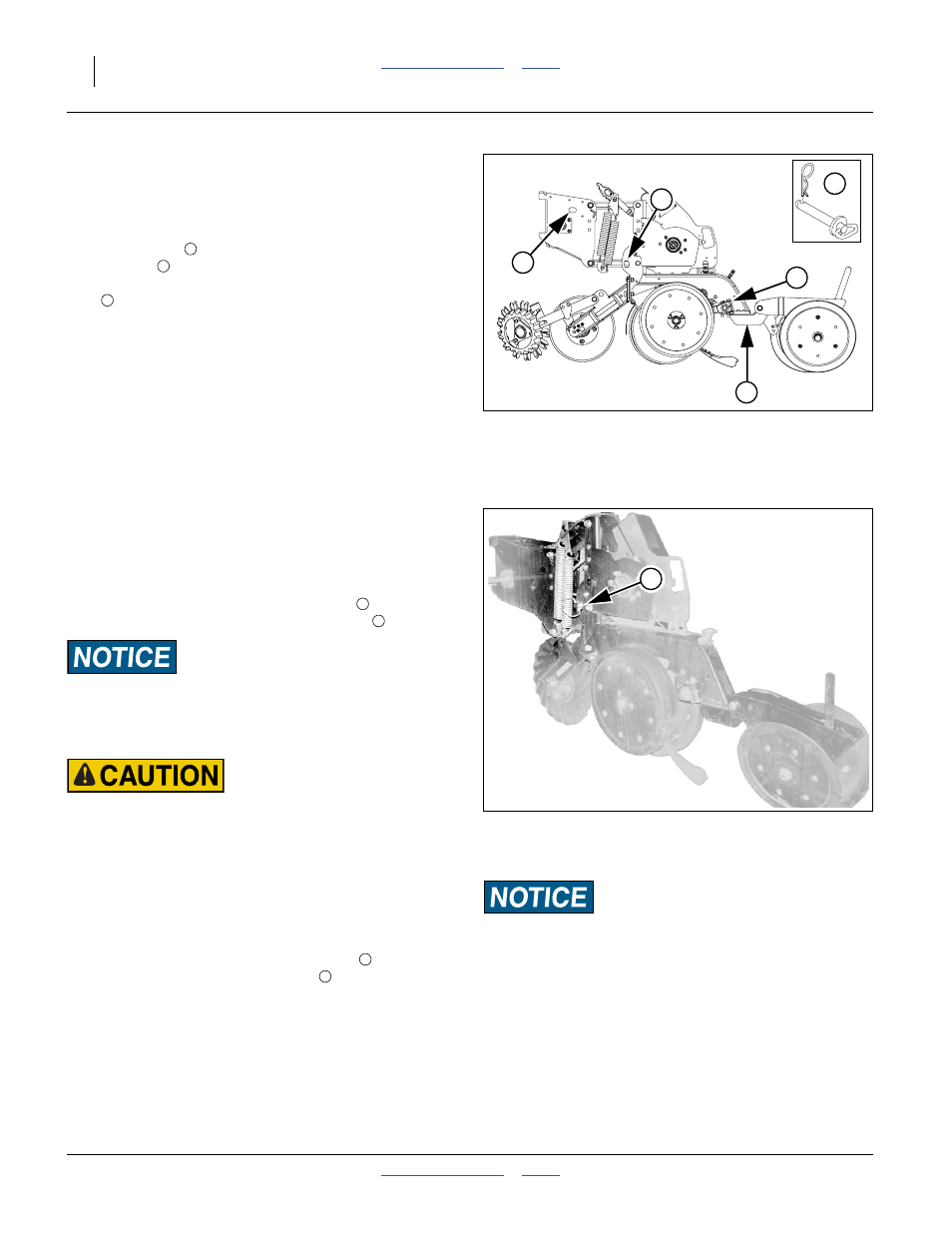
Refer to Figure 70
6.
Remove the pin from the storage hole
and secure it in the lock-up hole
7.
Lower row unit until lower parallel arm rests on
lock-up pin.
8.
Shut off Y-tube port for the current row unit.
9.
Disengage meter coupler.
10. Repeat for all rows needing lock-up.
Figure 69
25 Series Row Unit
Lock-Up Pin
25269
25118
2
3
5
4
1
Machine Damage Risk:
Do not pin the row unit while it is in the lowered position.
If the pin is inserted below the parallel arm, unit damage will
occur when planting begins.
Figure 70
25 Series Row Unit
Locked Up
25270
5
2
3