Fertilizer relief valve, Ground drive fertilizer pump – Great Plains 3PYP Operator Manual User Manual
Page 63
Great Plains Manufacturing, Inc.
Adjustments
59
2014-09-09
401-312M
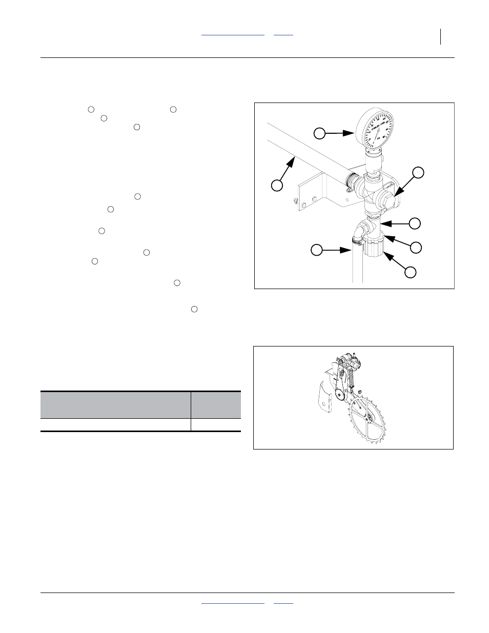
Fertilizer Relief Valve
Refer to Figure 60
A relief valve
and pressure gauge
the fertilizer inlet
connection point to the tractor, and
provides the fertilizer feed
to the manifold (manifold
not shown). The relief valve protects the manifold, lines
and fittings from excessive pressure. Any product that
dumps over the relief valve will discharge from the dump
line
➄
in relative safety, rather than appearing
unpredictably at some random point in the system.
To set relief valve:
1.
Unlock plastic jam nut
from relief valve knob.
2.
Unscrew knob
clockwise (looking down) until it
loses contact with internal spring.
3.
Screw knob
counterclockwise two turns.
Start at this setting.
4.
Observe manifold gauge
and watch for relief valve
dump line
discharge while operating in the field.
5.
If valve is dumping product and gauge reads under
85 psi, stop tractor and turn knob
clockwise
1
⁄
4
turn. Continue operating at normal field speed.
Repeat this step as needed until no product is
discharged from relief valve dump line
6.
If the pressure gauge reads above 85 psi, change to
a larger orifice. Go to step 2 and repeat.
Ground Drive Fertilizer Pump
Planters ordered without a fertilizer pump system, or
which have an older shaft-driven pump may be upgraded
to ground drive CDS-John Blue
®
piston pump:
For operations, see the Seed Rate manual.
Option Packages
Part
Number
3PYP JB GND DRV PSITON PMP ASM
407-422A
Figure 60
Fertilizer Relief Valve
25164
3
1
6
7
5
4
2
2
4
7
5
28416