Bleeding lift hydraulics, Lift bleed: s/n a1025s – Great Plains 3PYP Operator Manual User Manual
Page 105
Great Plains Manufacturing, Inc.
Maintenance and Lubrication
101
2014-09-09
401-312M
Bleeding Lift Hydraulics
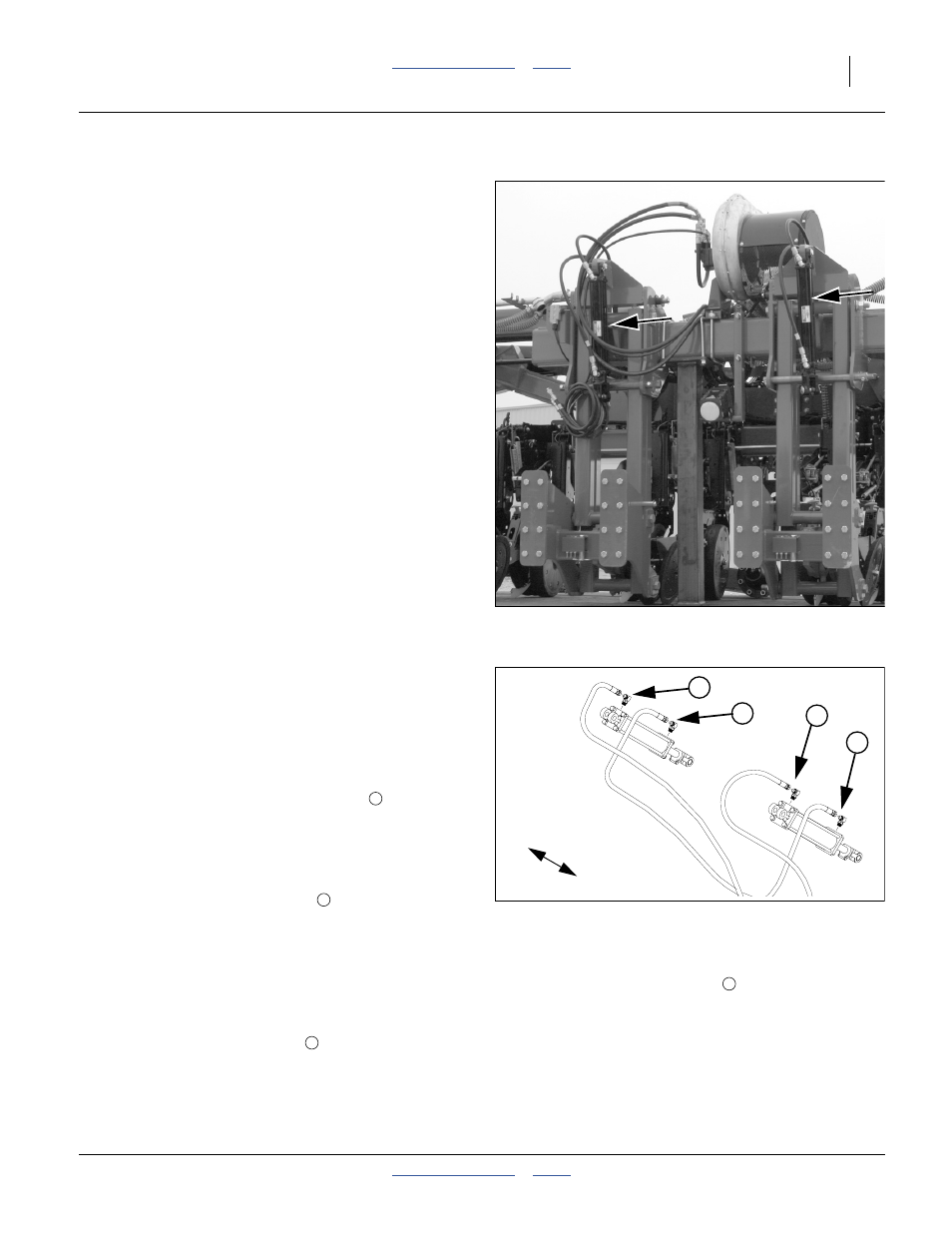
Refer to Figure 127 and Figure 128. Figure 127 depicts the
parallel arms disconnected from the seed support structure.
Disconnect only the cylinder rod end for bleeding.
Normally the lift hydraulics are bled at the factory before
shipping, and bleeding should not be required other than
to raise fully and hold lever on for one minute or until all
cylinders extend fully.
If the planter has wing flex cylinders or hydraulic down
pressure, bleed the small cylinders at the wing/center
coupling before bleeding the lift circuit. See “Bleeding
Wing Flex Hydraulics” on page 102
If necessary to further bleed system, follow these steps.
1.
Consult the lift circuit hydraulic diagram for your
planter:
“Lift with Wing Flex, s/n A1025S+”, page 132
“Lift with Wing Flex Lock (s/n A1025S+)”,
page 133
“Lift with Hydraulic Down-Pressure (S/N
A1025S+)”, page 134
“Lift with Hydraulic Down-Pressure (S/N A1025S+)
page 134
(both partially repeated here for reference)
2.
Check that tractor hydraulic reservoir is full. Set
hydraulics for low flow rate.
3.
Lower planter.
Lift Bleed: s/n A1025S+
If your planter is serial number A1024S or lower, see
“Appendix D: Older Equipment” on page 158.
4.
Disconnect and lower rod ends of lift assist cylinders.
5.
Extend the lift circuit until rods are fully extended. Set
circuit to Neutral.
6.
Loosen the JIC fitting at the base end
(top) of the
left lift cylinder.
7.
Extend the lift circuit again until fluid appears at the
loosened fitting. Set control lever to Neutral and
secure the fitting.
8.
Loosen JIC fitting at base end
of right lift cylinder.
9.
Extend the lift circuit until fluid appears at the
loosened fitting. Set lever to neutral. Secure the
fitting.
10. Retract the cylinders. Set circuit to Neutral. Elevate
both cylinders until the rod ends are higher than the
base ends.
11. Loosen JIC fitting at rod end
of the left lift cylinder.
12. Retract the lift circuit again until fluid appears at the
loosened fitting. Set control lever to neutral and
secure the fitting.
13. Loosen JIC fitting at rod end
of right lift cylinder.
14. Retract the lift circuit again until fluid appears at the
loosened fitting. Set control lever to neutral and
secure the fitting.
15. Re-pin cylinders to seed cart lugs.
Figure 127
Lift Assist Cylinders
29209
Figure 128
A1025S+ Lift Cylinders
29112
L
R
1
2
3
4
1
2
3
4